Industrial relay are indispensable components in automation control systems, and understanding Industrial Relay Symbol system is crucial for ensuring design quality, operational safety, and efficient troubleshooting. This guide offers a deep dive into the structure, application rules, and development trends of relay symbols. It draws on international standards (IEC 60617), domestic regulations (GB/T 4728), and real-world examples to provide actionable insights for equipment selection, circuit design, and fault diagnosis.
The Engineering Value of Industrial Relay Symbol
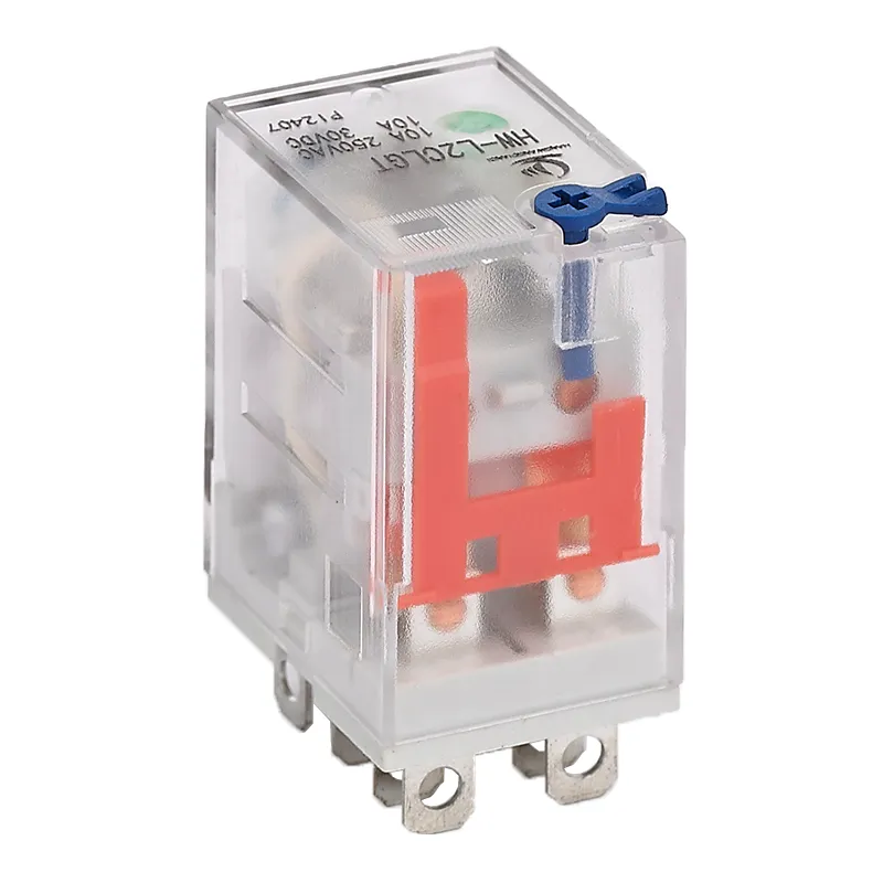
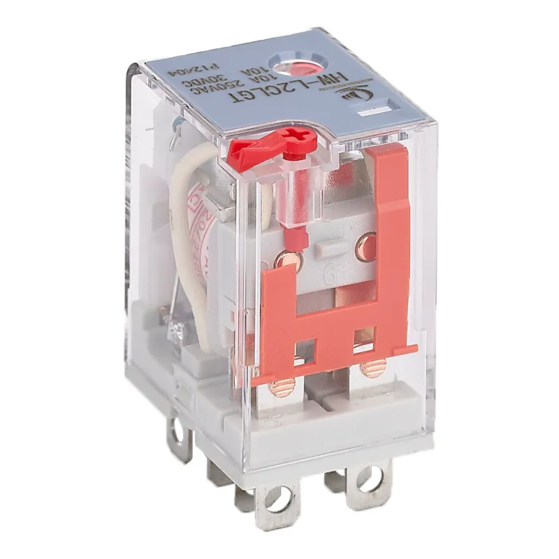
HW-L2CL Industrial Relay Symbol are more than just shapes on a schematic, they are the language of control systems. Misinterpreting these symbols can lead to costly errors. For instance, in 2023, a car production line faced a halt due to confusion over relay symbols, resulting in losses exceeding $300,000. This example underscores the importance of understanding relay symbols across three critical dimensions:
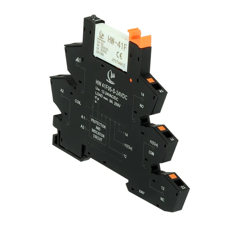
HW-L2CL LED Indicator Relay
Functional Identification: Relay symbols visually communicate the type of contact (e.g., normally open [NO/H-type] or normally closed [NC/D-type]). A simple 45° slanted line can determine whether a circuit remains open or closed when idle—a small detail with significant implications.
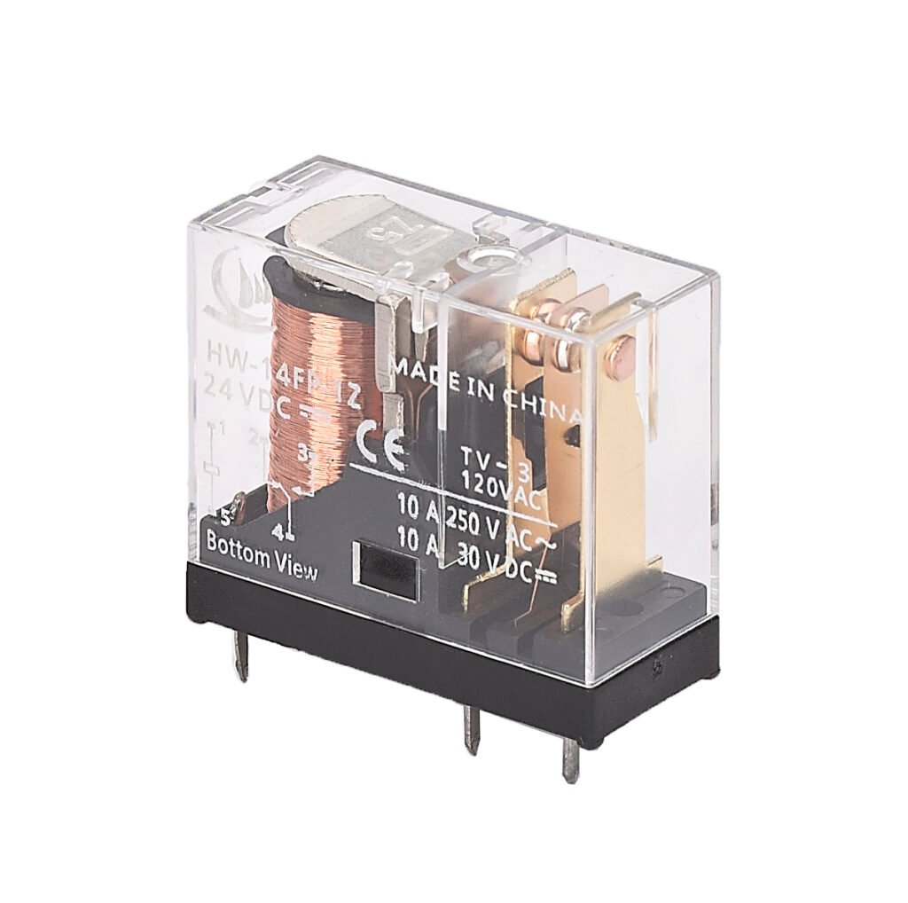
Parameter Identification: Symbols often include annotations like voltage ratings (e.g., “24VDC ±10%”). These details help engineers ensure compatibility with environmental conditions and prevent issues like coil overheating or overloading.
Safety Identification: Double-break symbols with parallel slanted lines indicate compliance with IEC 60947 standards for forced disconnection capability—a critical feature for designing safety circuits in industrial environments.
Why Standardization Matters
Standardized Industrial Relay Symbol have streamlined engineering workflows. Between 2010 and 2024, adopting updated IEC symbols reduced design errors from 32% to 9%. However, compatibility issues persist across manufacturers, requiring engineers to be adept at recognizing both universal rules and specific variations.
Topological Structure and Evolution of Industrial Relay Symbol
Relay symbols are rooted in electromagnetic principles and exhibit modular characteristics that make them versatile yet precise. Understanding their structure is key to decoding their meaning.
Morphological Analysis of Coil Symbols
Coil symbols represent the “heart” of a relay, where electromagnetic force activates the contacts. Standard coil symbols are rectangular boxes with a width-to-height ratio of 1:2.5 for readability. Variations include:
Polarized Coils: An arrow (→) is added to indicate the magnetic pole direction.
Dual-Winding Coils: Two parallel rectangular boxes labeled W1/W2 show multiple windings.
Energy-Saving Coils: A wavy line within the rectangle indicates latch retention features.
Annotations around coil symbols provide critical information:
Voltage Ratings: Displayed above the symbol (e.g., “24V”).
Power Consumption: Shown on the left (e.g., “2W”).
Insulation Grade: Marked below (e.g., “F-class”).
These annotations allow engineers to match relays with system requirements at a glance.
Dynamic Modeling of Contact Symbols
Contact symbols represent how circuits open or close under specific conditions:
Normally Open Contacts (H-type): A gap between static and moving contacts is depicted with a slanted line at a precise angle of 45° ±2°.
Normally Closed Contacts (D-type): A solid circle represents continuous contact.
Changeover Contacts (Z-type): The moving contact’s swing radius mirrors the coil’s width.
For delayed contacts, time parameters such as “τ=50ms” are annotated alongside exponential curves to indicate timing behavior.
Symbols for various types of relay
Each relay has its own specific graphic symbols, which usually include graphic representations of input, output and operating parts. Through these symbols, we can intuitively understand the structure and working principle of the relay.
Time relay symbol: left is power-off delay, right is power-on delay
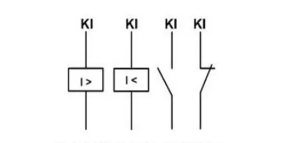
Current relay symbol: left is overcurrent, right is undercurrent
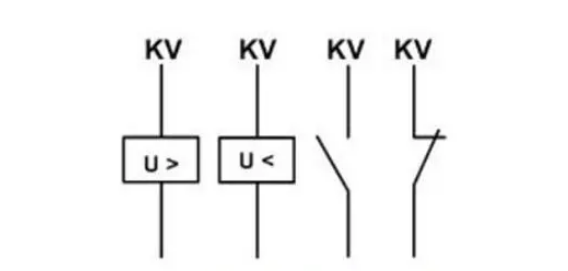
Voltage relay symbol: left is overvoltage, right is undervoltage
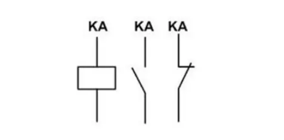
Intermediate relay symbol
Request free samples and see the quality of our relay products. Get a free quote today for industrial relays that meet your specs.
For example, in 2024, a power substation experienced cascading trip failures due to incomplete parameter annotations on timing relays—a costly reminder of why precision matters.
Typical Application Scenarios
Relay symbol systems shine brightest when applied effectively:
Smart Manufacturing Production Lines
In an automotive welding line, optimizing relay symbol schemes reduced drawing error rates by 40%. Improvements included:
As Industrial Relay Symbol engineering becomes more intelligent, design efficiency could improve by up to 300%.
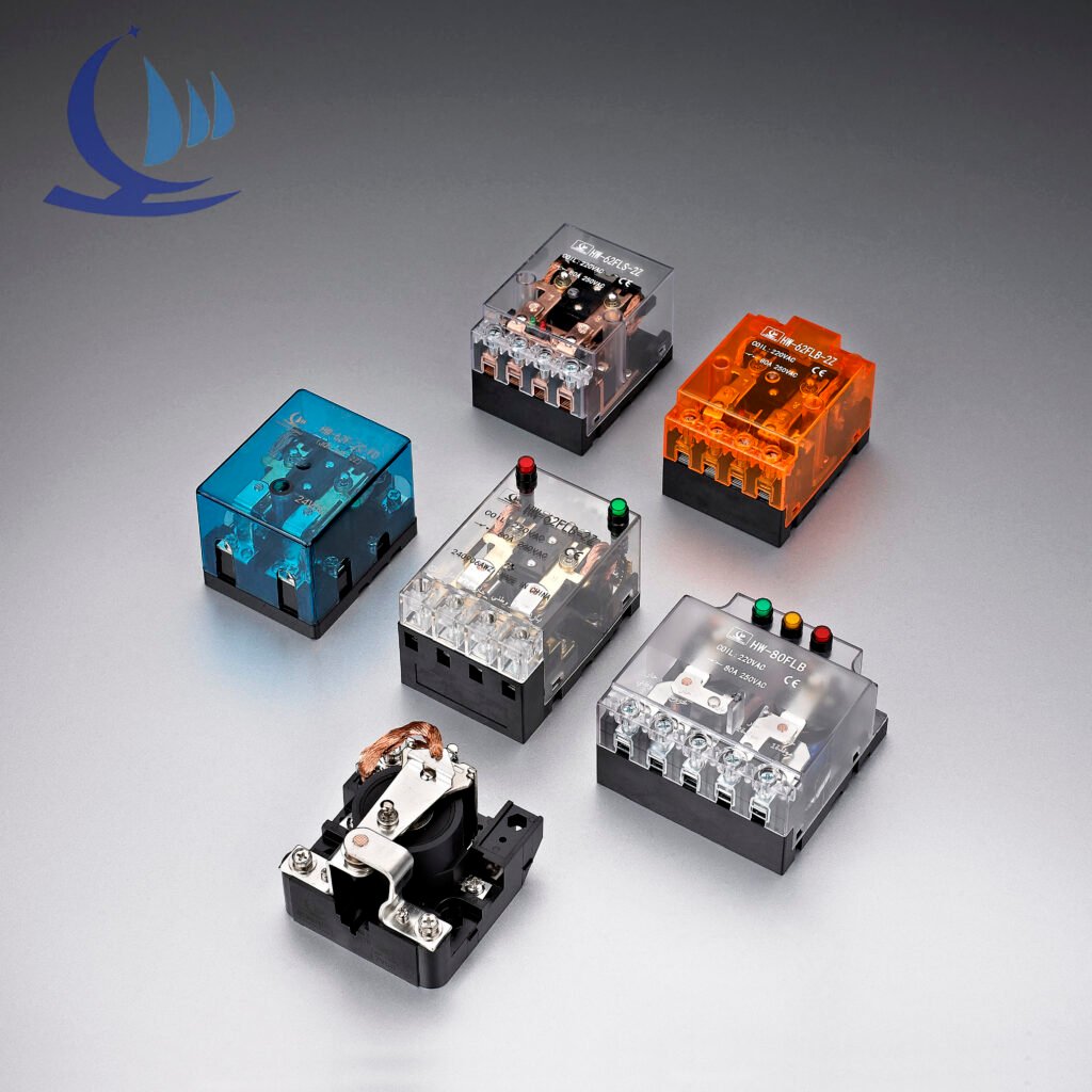
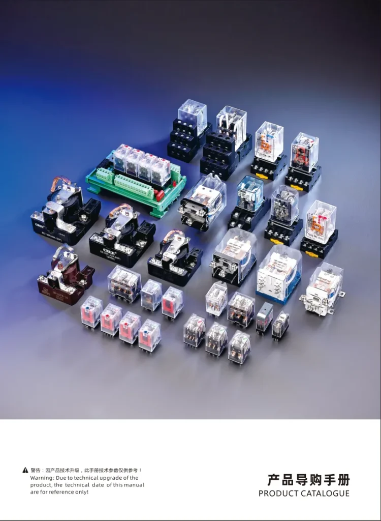
At hwrelay, we focus on high-quality relay solutions tailored for different business needs. Whether you need electromagnetic relays, industrial relays, intermediate relays, or small relays, we have it all here. If you are interested in our industrial relay, then click the link to contact our professionals, we can help you purchase the right product target.
Contact us now, and look forward to hwrelay working with you to make progress together and achieve win-win results!
FAQ
What does a relay coil symbol represent?
The coil symbol shows the electromagnetic part of the relay that activates the switching contacts when energized. It’s often drawn as a rectangle or circle.
What is the meaning of Normally Open (NO) and Normally Closed (NC) contacts in relay symbols?
NO contacts are open when the relay is off and close when energized, allowing current flow. NC contacts are closed when off and open when energized, interrupting current.
What are common relay forms shown in symbols?
Form A is normally open; Form B is normally closed; Form C combines both NO and NC contacts in one relay for more versatile switching.
How do relay symbols help in circuit design?
They provide a visual shorthand that simplifies wiring, troubleshooting, and understanding relay operation in electrical schematics.
In the fast-moving world of industrial automation, reverse power relay are small but crucial components that safeguard generators and parallel power systems. If you’re an engineer, electrical system designer, or purchasing manager, understanding how this device works—and how to select the right one—can help you prevent expensive downtime, hazardous faults, and unnecessary wear on your equipment. Let’s explore what makes […]
Have you ever felt confused by Industrial Relay contact symbols when designing industrial automation systems? Or hesitated during selection, unsure which contact type best fits your project? Don’t worry—this article will take you on a deep dive into Industrial Relay Contact types, symbols, and their specific roles and advantages in industrial applications. By mastering these essentials, you’ll […]
Working principle of small relay A small relay is an electrical switch that operates using the principle of electromagnetic induction to control the on and off states of a circuit. It typically consists of four main components: a coil, an iron core, an armature, and contacts. When the coil is energized, current flows through it, generating a magnetic field. […]
We use cookies to enhance your browsing experience, serve personalised ads or content, and analyse our traffic. By clicking "Accept All", you consent to our use of cookies.
Get a Free Quote
Your email information is completely secure and will not be disclosed to third parties for any reason.
Interested In Our Relay Products?
Get the latest product brochures and technical data.