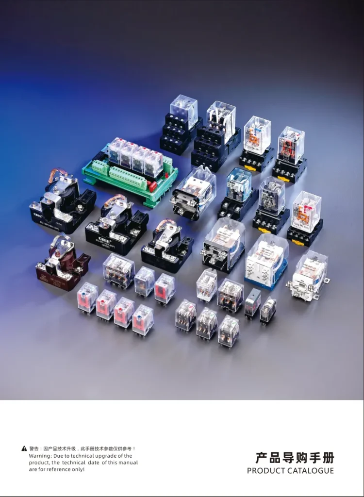
Relay symbols are the cornerstone of electrical engineering, the universal language for designing, troubleshooting, and maintaining electrical systems. Whether you’re drawing a residential circuit or a complex industrial control panel, understanding these symbols ensures clarity and accuracy. This article will take you through relay symbols, covering their definitions, components, types, and global standards. By the end, you’ll be able to confidently interpret and apply these symbols to any project.
What Are Relay Symbols?
Definition and Role in Electrical Schematics
Relay symbols are graphical representations used in electrical diagrams to denote the presence, function, and connection points of relays. They simplify complex circuits by abstracting physical components into standardized icons, enabling engineers worldwide to collaborate seamlessly.
Standardization
Standardization Bodies :
IEC 60617: The global standard for electrical symbols, widely adopted in Europe and Asia.
ANSI/IEEE C37.2 : The U.S. standard, emphasizing compatibility with North American systems.
Regional Variations : Examples include JIS (Japan) and GB/T (China) for localized compliance.
Impact on Electrical Design
Without standardized symbols, engineers would need to reinvent representations for every relay type, leading to confusion and errors. Symbols streamline collaboration, reduce misinterpretation, and ensure safety in high-voltage systems.
Practical Guide — How to Read Relay Symbols in a Schematic
When you encounter a relay symbol on a schematic diagram, follow these four steps:
Identify the coil terminals — Find the two pins labeled with the coil symbol (rectangular for IEC, zigzag for ANSI).
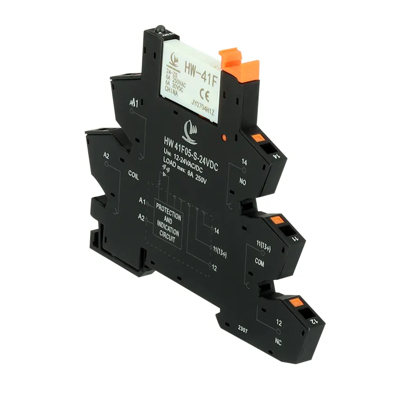
Locate the COM (common) terminal — This is the input pin for the load-side current.
Identify NO (Normally Open) and NC (Normally Closed) contacts — Remember: “normal” refers to the coil de-energized state. NO contacts are drawn as open; NC contacts as closed.
Trace the switching path — Follow the current path in both the energized and de-energized states to verify your circuit logic.
Pro tip: Always confirm pin assignments against the relay datasheet before finalizing your schematic. Different manufacturers may assign different functions to the same physical pin positions.
Relay Basics Key Components and Their Functions
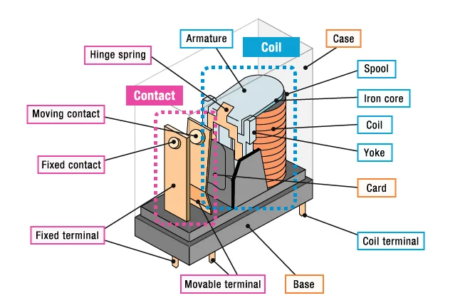
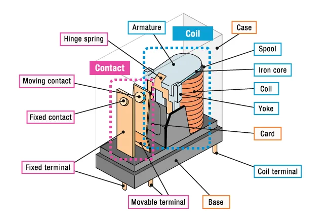
Relay symbols are built from core elements that define their operation. Below are the Hangwang Electrical Relay supplier essential components:
1. Coil Symbols
Representation : A rectangular box labeled with “COIL” or “LC” (Line Coil).
Function : Indicates the electromagnetic component that activates the relay when energized.
Labeling : Often includes voltage ratings (e.g., 24V DC) and terminal connections.
2. Contact Symbols
Normally Open (NO) Contacts :
Symbol: A diagonal line with a short horizontal line (like —|/)
Function: Contacts close when the coil is energized.
Normally Closed (NC) Contacts :
Symbol: A diagonal line with a short vertical line (like—|\)
Function: Contacts open when the coil is energized.
Changeover (CO) or Double Throw (DT) Contacts :
Symbol: Combines NO and NC contacts in a single symbol.
Function: Switches between two outputs (e.g., switching between power sources).
Relay contact symbol
3. Terminal Symbols
Input/Output Connections : Dots or labels (e.g., “L1,” “L2”) denote where wires connect to the relay.
Ground and Power Supply : Ground symbols (⏚) and power supply symbols (⎓) clarify circuit pathways.
4. Timing and Specialized Relays
Time-Delay Relays :
Symbol: A coil with a “T” or “TD” label.
Function: Adds a delay before activating contacts (e.g., in motor startups).
Latching Relays :
Symbol: A coil with an “L” or “RST” (reset) terminal.
Function: Maintains state after power loss until manually reset.
Solid-State Relays :
Symbol: A coil with a diode-like symbol (like ▷), indicating no moving parts.
Relay symbols are the backbone of electrical engineering, enabling clear communication across borders and industries. By mastering their components, types, and standards, engineers can design safer, more efficient systems.
Looking for a reliable supplier of high-power power relays? HW RELAY provides high-quality relay products, technical specifications, and OEM/ODM solutions for overseas markets. Contact us for bulk pricing.
Relay Symbols in Ladder Logic Diagrams
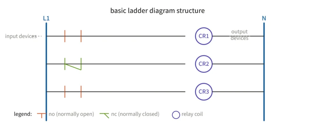
In industrial automation, relay symbols often appear inside ladder logic diagrams — the standard programming language for PLCs. In a ladder diagram:
The two vertical rails represent the power supply (L1 and L2 or +24V and 0V).
Horizontal rungs contain contact symbols (inputs) on the left and coil symbols (outputs) on the right.
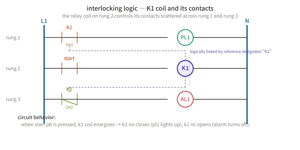
A relay coil on one rung can control its contacts on multiple other rungs, allowing complex interlocking logic.
This is distinct from traditional schematic symbols — the coil and its associated contacts may be scattered across different rungs, linked only by the reference designator (e.g., “K1”).
Relay Symbols in Real Circuits — Practical Examples
Knowing individual symbols is one thing; reading them in context is another. Below are three common circuit patterns you will encounter frequently.
Example 1: Microcontroller-Driven Relay A low-power MCU pin cannot drive a relay coil directly. A transistor (e.g., 2N2222) is placed between the MCU output and the relay coil. A flyback diode (1N4148 or 1N4007) is connected in reverse parallel across the coil terminals to suppress the voltage spike generated when the coil de-energizes — without it, the transistor would be destroyed.
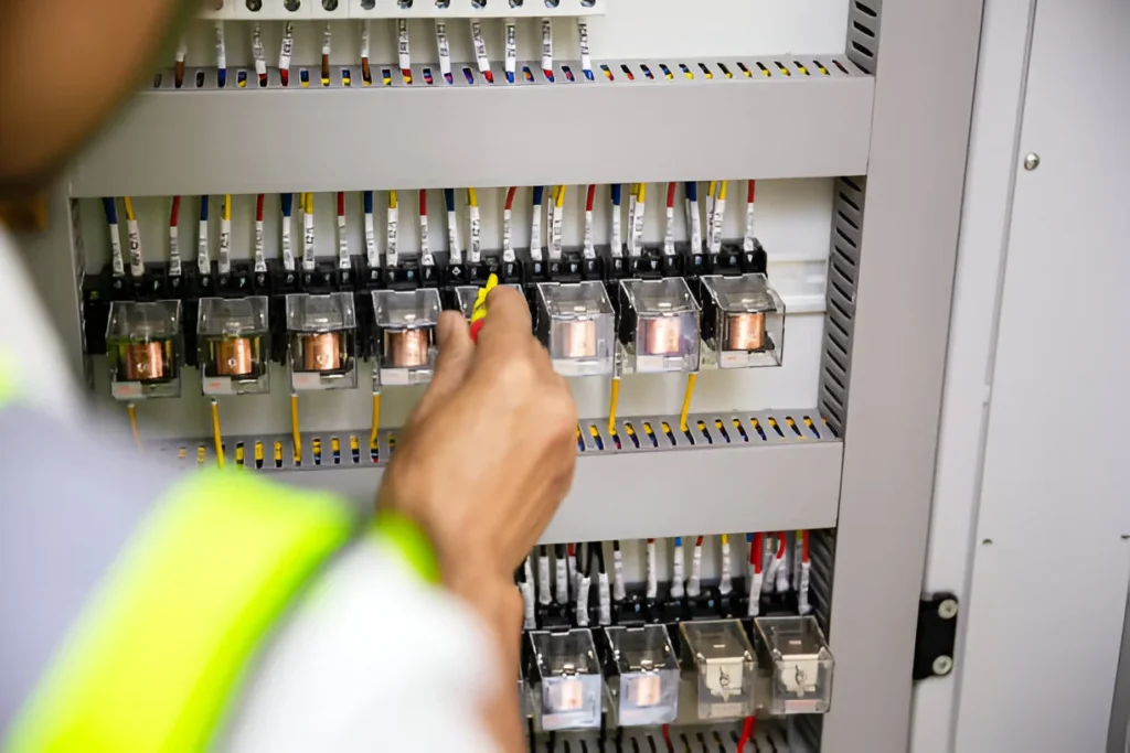
Example 2: High-Voltage Isolation In a typical control panel schematic, the relay symbol clearly separates the 24V DC control side (coil) from the 240V AC load side (contacts). This visual separation reinforces the physical isolation that the relay provides — a key safety feature in industrial designs.
Example 3: Motor Start/Stop with Latching A latching relay symbol includes two coils — “SET” and “RESET” — each drawn as a separate rectangle. The contacts change state when the SET coil is pulsed and remain in that state even after power is removed, until the RESET coil is pulsed. This is commonly used in energy-saving applications such as smart meters and building automation.
Common Mistakes When Using Relay Symbols in PCB Design
Through analyzing real-world design failures, these are the most frequent errors engineers make:
Confusing NO and NC assignments — A heater connected to the NC contact will remain ON during a system fault, creating a safety hazard.
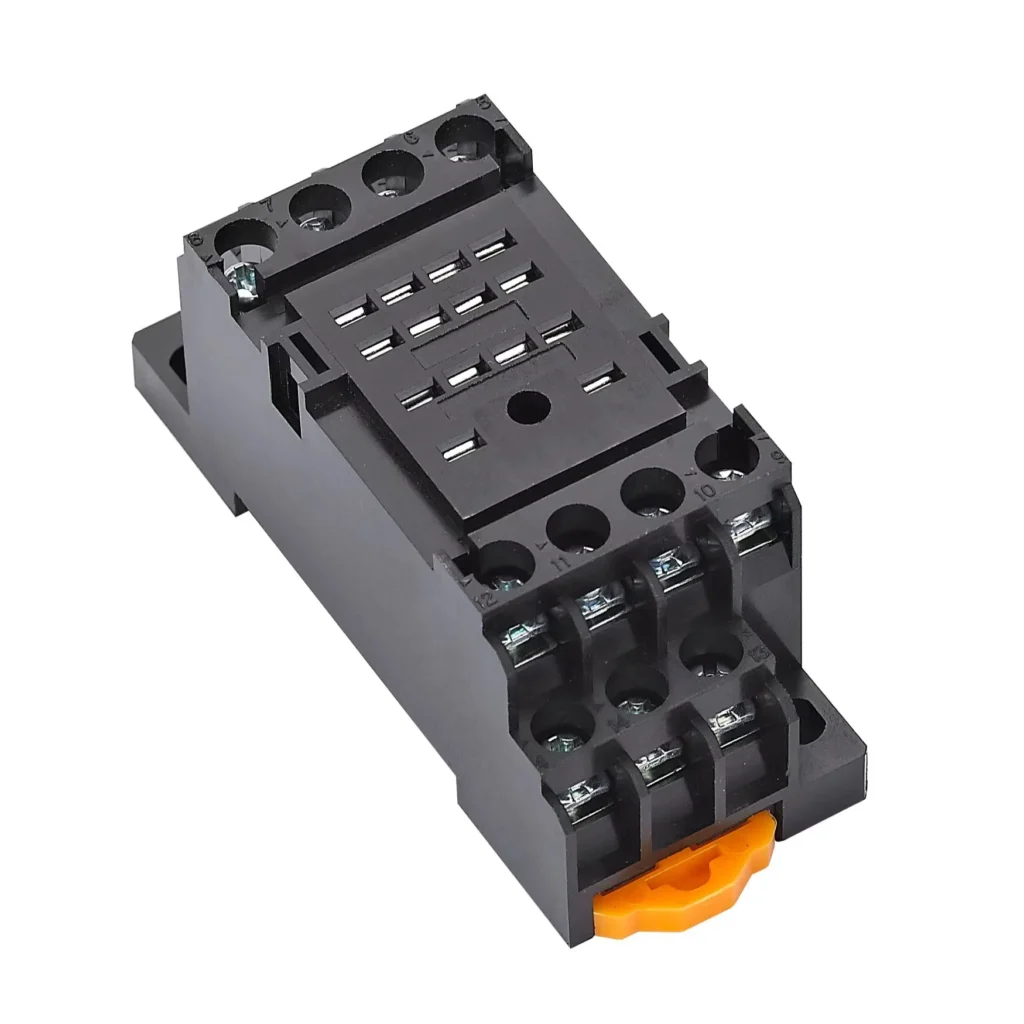
Pin mapping mismatch — The logical symbol pinout does not match the physical package, making assembly impossible.
Missing flyback diode — Driving a relay coil without a reverse-biased diode destroys the driving transistor.
Insufficient creepage distance — For 240V AC applications, maintain at least 6mm clearance between high-voltage and low-voltage traces (per IEC 60950).
Wrong package selection — Using a signal-relay footprint for a power-relay application leads to trace overheating and PCB damage.
Mastering relay symbols is the first step, Choosing the right relay is the next. HW Relay offers a full range of industrial-grade relays designed for automation systems. Browse our catalog and find your perfect match.
FAQ
What are the most common relay symbols in electrical diagrams?
The most common are: NO/NC contacts (—|/ and —|). Coil symbols (rectangular boxes with labels). Ground symbols (⏚).
How do I differentiate NO and NC contacts?
NO contacts (—|/) are open by default and close when energized. NC contacts (—|) are closed by default and open when energized.
Are relay symbols standardized globally?
Yes, but regional standards (IEC, ANSI) may differ slightly. Always confirm the project’s required standard.
Where can I find resources to learn more?
IEC 60617 Manual The definitive guide for international standards. Electrical Technology Blogs Examples include Electrical Technology for practical examples.
In this article, I’m going to walk you through one of the most practical workhorses in industrial control panels: the Power Relay power control module relay family that includes the HW‑30F‑2Z. You’ll get clear wiring guidance, selection rules, and real‑world tips that you can actually plug into your next project. If you’ve ever stared at an 8‑pin relay […]
Understanding Relay Modules Relay modules are compact circuit boards housing one or more relays, typically rectangular in shape. These modules come in various configurations, accommodating 2, 4, 8, or even up to 16 relays. Beyond the relay units, these modules incorporate additional components such as indicator LEDs, protection diodes, transistors, and resistors. At the heart […]
If you’re here, you probably already know that an intermediate relay 5A is one of the most common “workhorses” in control panels. But in the real world, B‑end buyers don’t just care about definitions—they want to know how to pick the right model, how to wire it properly, and where to use it without causing headaches down […]
We use cookies to enhance your browsing experience, serve personalised ads or content, and analyse our traffic. By clicking "Accept All", you consent to our use of cookies.
Get a Free Quote
Your email information is completely secure and will not be disclosed to third parties for any reason.
Interested In Our Relay Products?
Get the latest product brochures and technical data.