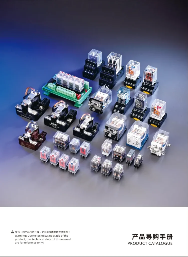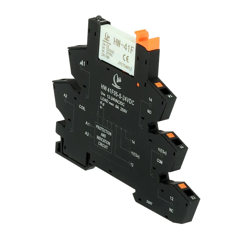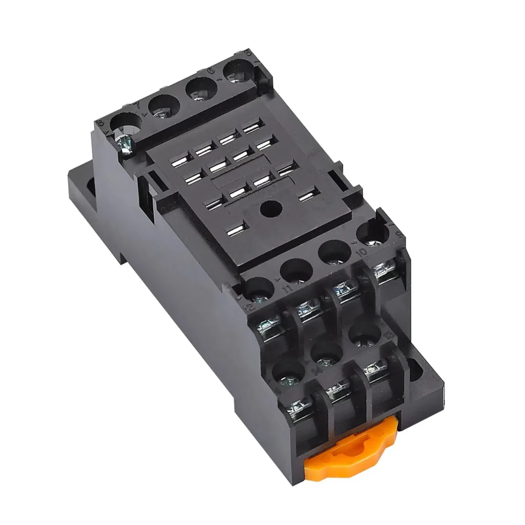
General Purpose Relay
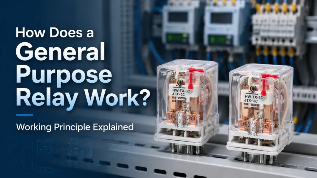
How Does a General Purpose Relay Work?
A step-by-step guide to the electromagnetic working principle of general purpose relays, covering coil operation, contact switching, AC/DC differences, and failure mechanisms.
Read More
A general purpose relay is an electrically operated switch that uses a low-power control signal to open or close one or more higher-power load circuits through electromagnetic action. If you have ever worked with control panels, HVAC equipment, industrial automation, or household appliances, you have almost certainly encountered these versatile switching devices. This guide covers what a general purpose relay is, how it works, key specifications, common contact configurations, selection guidance, and real-world applications—so you can specify the right relay with confidence.
A general purpose relay is an electromagnetic switching device that electrically isolates a control circuit from a load circuit. When a small voltage is applied to the relay coil, it generates a magnetic field that physically moves an armature, changing the state of one or more sets of contacts. This lets a PLC, thermostat, sensor, timer, or push-button switch control a completely separate circuit—often at a different voltage or current level.
The term “general purpose” reflects the relay’s broad applicability. Unlike specialty relays designed for a single function (such as overload protection or automotive-specific duties), HWrelay general purpose relay fits a wide range of switching tasks across industrial, commercial, and consumer equipment. It is not inherently a protection device—fuses, circuit breakers, or overload relays must handle fault conditions separately.
The operating principle is straightforward but effective. Here is what happens step by step:
Because the control coil and the load contacts are electrically isolated, a fault or surge on the load side does not directly reach the controller. This isolation is one of the relay’s most valuable characteristics.
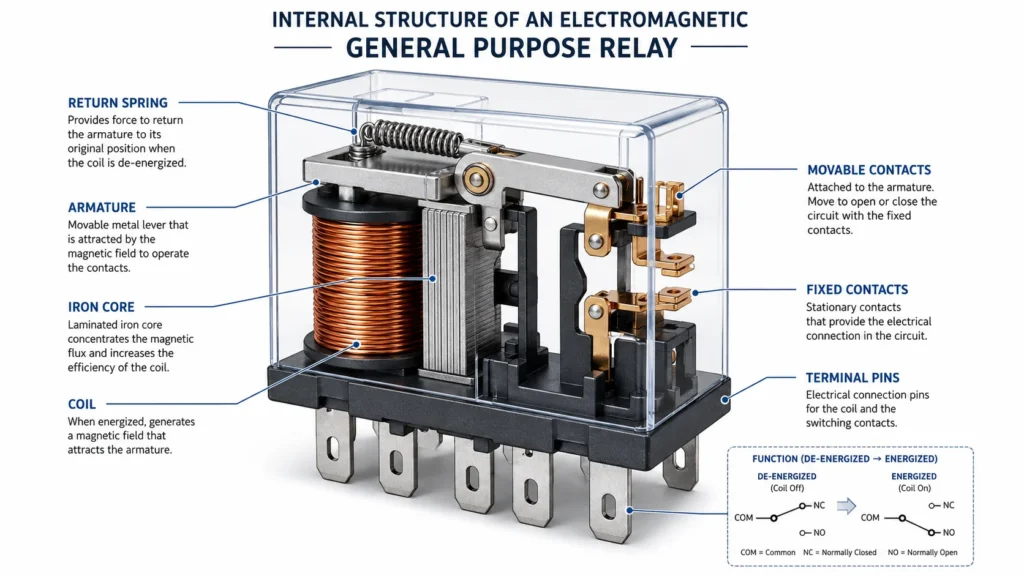
Understanding the internal structure helps you evaluate relay quality, read datasheets, and troubleshoot circuits. A typical general purpose relay contains:
| Component | Function |
|---|---|
| Electromagnetic coil | Generates the magnetic field when energized; wound with insulated copper wire |
| Iron core and yoke | Concentrates and guides magnetic flux; made from laminated silicon steel to reduce eddy current loss |
| Movable armature | Mechanically linked to the contacts; attracted by the energized core |
| Return spring | Returns the armature to its default position when the coil is de-energized |
| Contact sets (NO, NC, COM) | Silver-alloy contacts that make or break the load circuit; designed for low resistance and arc resistance |
| Protective enclosure | Dust cover or sealed case that protects internal parts from contamination |
| Terminals / pins | Connection points for coil power and load wiring; available as plug-in pins, PCB pins, or screw terminals |
Contact configuration describes how many circuits a relay can switch and what happens to each contact when the coil is energized. The terminology follows standard switch notation.
| Configuration | Abbreviation | What It Means |
|---|---|---|
| Single-Pole Single-Throw (Normally Open) | SPST-NO / 1H / Form A | One circuit; contact closes when energized, opens when de-energized |
| Single-Pole Single-Throw (Normally Closed) | SPST-NC / 1D / Form B | One circuit; contact opens when energized, closes when de-energized |
| Single-Pole Double-Throw | SPDT / 1Z / Form C | One circuit with COM, NO, and NC terminals; switches between two paths |
| Double-Pole Double-Throw | DPDT / 2Z | Two independent changeover circuits operated by a single coil; eight terminals total |
| Three-Pole Double-Throw | 3PDT / 3Z | Three independent changeover circuits; useful when multiple signals must switch simultaneously |
DPDT (2Z) and 3PDT (3Z) are the most common configurations in general purpose relay product lines, providing flexibility for most control and signal-switching requirements. A single relay with multiple poles can replace two or three separate relays in many circuits.
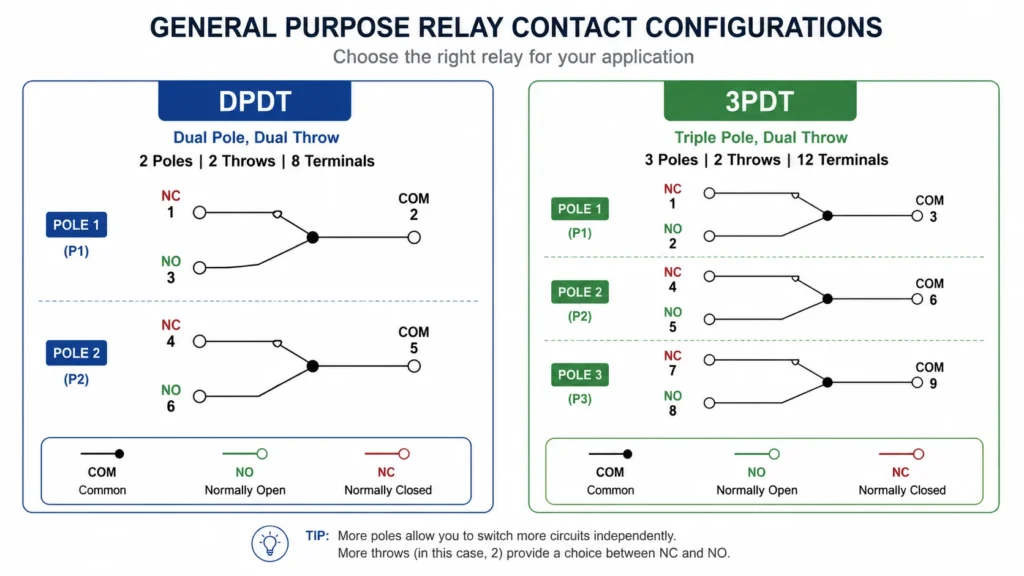
When you review a general purpose relay datasheet, focus on these five parameters first:
Coil voltage is the control signal voltage required to energize the relay. Common values include 5V, 12V, 24V, 48V, 110V, and 220V. An AC coil and a DC coil rated at the same voltage are not interchangeable—an AC 24V relay cannot replace a DC 24V relay because their internal coil construction differs. Always match both the voltage value and the supply type (AC or DC) to your control circuit.
Contact rating specifies the maximum current and voltage the relay contacts can safely switch. For a 10A general purpose relay, the resistive load rating is typically 10A at 240VAC or 28VDC. However, for inductive loads (motors, solenoids, transformers), the maximum switching load is lower—for example, 240VAC 5A or 28VDC 5A—due to inrush currents and arcing during contact opening. Always derate for inductive loads and confirm ratings with your specific voltage, load type, switching frequency, and expected electrical life.
As covered above, select the number of poles and throws your circuit requires. A DPDT (2Z) relay gives you two changeover contacts in one package; a 3PDT (3Z) gives you three.
General purpose relays are available in several mounting styles:
Many general purpose relays offer additional features that simplify commissioning and troubleshooting:
It helps to know where a general purpose relay fits among the broader relay family before you make a selection.
| Relay Type | Typical Contact Rating | Best For | Key Difference |
|---|---|---|---|
| General Purpose Relay | 5A–10A | Control panels, signal switching, HVAC interfaces, appliance control | Versatile; wide coil voltage range; multiple contact configurations |
| Power Relay | 25A–60A+ | Motors, transformers, heaters, high-current industrial loads | Higher current capacity; larger form factor; may require a contactor for very high loads |
| Intermediate Relay | 5A–10A | PLC output expansion, signal multiplication, control-logic interlocking | Often used to multiply or isolate PLC outputs; similar ratings but purpose-optimized for control-logic chains |
| Solid-State Relay (SSR) | Varies widely | High-speed switching, silent operation, frequent cycling | No moving parts; zero-crossing or random turn-on; requires heat sinking for higher currents |
| Automotive Relay | 20A–40A (12V/24V DC) | Vehicle lighting, fuel pumps, horns, fans | Designed for DC only; vibration-resistant; standardized blade terminals |
For most signal-level and moderate-load switching in control panels and automation equipment, a general purpose relay is the right starting point. When loads exceed 10A or involve heavy motor starting, a power relay or contactor becomes necessary. For PLC output expansion, an intermediate relay may be the better fit.
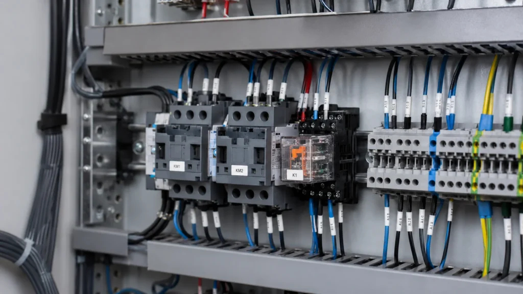
General purpose relays appear across nearly every industry that uses electrical control. Common deployment scenarios include:
Use this step-by-step checklist to narrow down your options and avoid common specification errors.
If you need help matching a relay to your specific application, reviewing the manufacturer’s selection guide or product catalog is a good next step.
| Mistake | Why It Happens | How to Avoid It |
|---|---|---|
| Using an AC coil on a DC supply (or vice versa) | Assumes “24V is 24V” without checking AC/DC type | Always verify both the voltage value and the supply type before ordering |
| Underrating the contact load for inductive circuits | Using the resistive rating for motors, solenoids, or transformer loads | Check the datasheet for the inductive/motor-load rating; derate or use a power relay for high-inrush loads |
| Skipping the wiring diagram | Assuming all relays use the same pinout | Consult the specific relay’s wiring diagram and socket pin arrangement before connecting |
| Ignoring contact suppression for DC coils | Not adding a flyback diode across a DC coil | Use a diode or an RC snubber to protect the driving transistor or PLC output from back-EMF spikes |
| Choosing a relay with too few poles | Buying an SPDT relay when the circuit needs two simultaneous changeovers | Count the number of independent circuits you need to switch; select DPDT (2Z) or 3PDT (3Z) accordingly |
A general purpose relay is a fundamental building block of electrical control. It provides reliable isolation between low-power control signals and the circuits they manage, fits a wide range of switching tasks, and offers enough contact-configuration flexibility to solve most day-to-day automation and equipment-design challenges. By matching your coil voltage, contact configuration, load rating, and mounting requirements carefully—and by checking the wiring diagram before you connect—you can avoid the most common specification and installation mistakes.
If you are sourcing general purpose relays for a project, OEM production, or panel build, explore the general purpose relay product range for DPDT and 3PDT options with AC and DC coil voltages, LED indicators, and optional test functions. For specific technical questions, model recommendations, or bulk pricing, you can contact the engineering team directly.
A general purpose relay typically handles 5A–10A contact loads and focuses on signal-level and moderate-load switching in control circuits. A power relay handles 25A–60A+ and is built for high-current loads such as motors, heaters, and transformers. When your load exceeds 10A, consider a power relay or contactor.
DPDT stands for Double-Pole Double-Throw. It provides two electrically independent changeover contacts operated by a single coil. Each pole has a COM, NO, and NC terminal, for a total of eight terminals including the coil. In many relay model codes, this is marked as “2Z.”
Yes. General purpose relays are widely used in HVAC applications for thermostat interfaces, fan control, damper actuation, compressor contactor coils, and building-automation signal routing. Make sure the relay is correctly rated for the actual load and inrush current of the equipment it controls.
It can switch a small motor only when the motor’s running current, starting (inrush) current, voltage, duty cycle, and power factor all stay within the relay’s motor-load rating. For most industrial motors and compressors, the general purpose relay should drive a contactor rather than switch the motor directly.
No. An AC 24V relay and a DC 24V relay have different internal coil constructions and magnetic-circuit designs. The AC coil uses a shading ring to prevent chatter at zero crossings. A DC coil connected to an AC supply may overheat; an AC coil on DC may not pull in reliably. Always match both the voltage value and the AC or DC supply type.
Terminal positions vary between relay series, socket types, and manufacturers. Checking the wiring diagram prevents incorrect coil connections, reversed NO/NC wiring, short circuits, and damage to the relay or the controller driving it.
An LED indicator makes it easy to confirm coil status during commissioning and troubleshooting. A test button or self-locking mechanism allows you to manually operate the contacts without energizing the coil—helpful during panel testing. Coil suppression (diode or RC circuit) protects PLC outputs and transistors from voltage spikes when the coil de-energizes.
A step-by-step guide to the electromagnetic working principle of general purpose relays, covering coil operation, contact switching, AC/DC differences, and failure mechanisms.
Read More