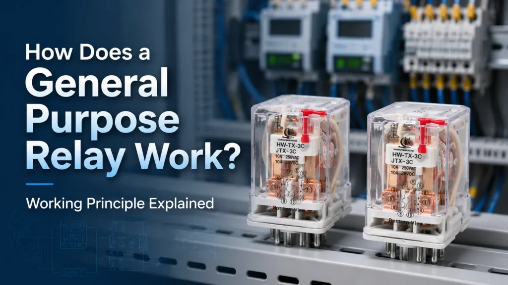
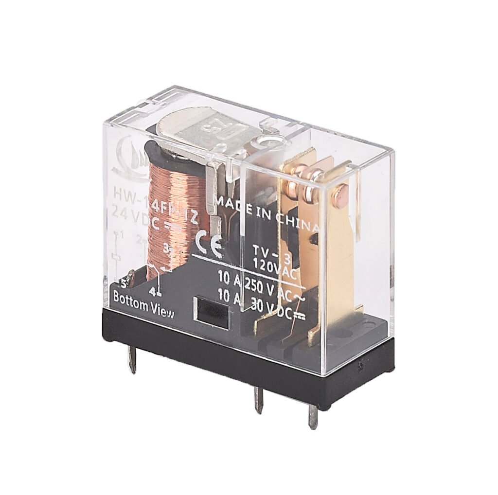
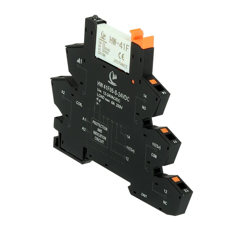
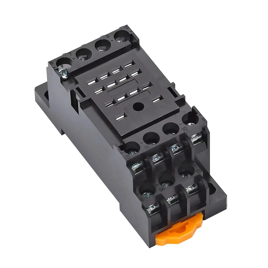
At its core, a General Purpose Relay is an electromagnetic device that converts a small electrical signal into mechanical motion to open or close switch contacts. Unlike a manual light switch operated by a finger, a relay is operated by a magnetic field—and that invisible force is what makes it useful for automation, isolation, and remote control. This article walks through exactly what happens inside a general purpose relay from the moment coil voltage is applied to the moment the contacts settle into their new state, covering both AC and DC operation.
The Basic Idea Electromagnetic Switching
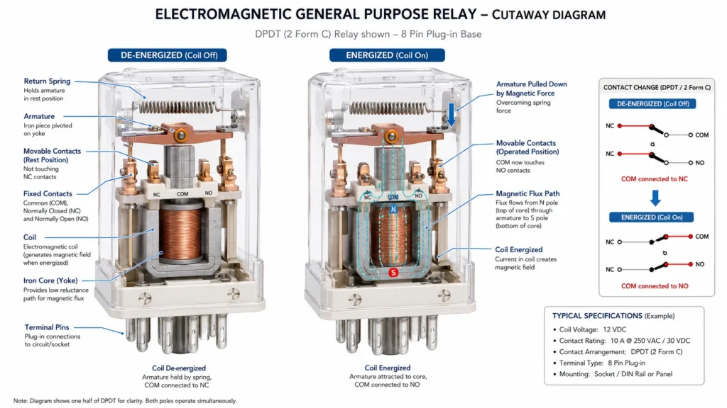
A general purpose relay separates a control circuit from a load circuit through electromagnetic coupling. On the control side, a coil of wire wrapped around an iron core acts as an electromagnet. On the load side, one or more sets of spring-loaded contacts rest in their default positions. The two sides share no electrical connection—only a magnetic one. When current flows through the coil, the resulting magnetic field physically pulls the contacts from one position to another. When current stops, a spring returns everything to its starting state.
This isolation is the relay’s fundamental value: a 5V microcontroller pin can safely switch a 240VAC pump, a thermostat can control a compressor, and a PLC output can drive a contactor coil—all without any direct electrical path between the low-power controller and the high-power load.
Inside a General Purpose Relay Core Components
Before tracing the switching cycle, it helps to identify the parts involved and their roles.
Component
Material
Role in Operation
Coil
Insulated copper wire, wound on a bobbin
Generates the magnetic field when energized; the number of turns and wire gauge determine the operating voltage
Iron core
Laminated silicon steel
Concentrates and amplifies the magnetic flux; lamination reduces eddy current losses
Yoke
Soft iron
Completes the magnetic circuit by providing a low-reluctance return path for flux
Armature
Movable soft iron piece
The part that physically moves when attracted by the energized core; mechanically linked to the moving contacts
Return spring
Spring steel
Holds the armature in the de-energized position; returns it when coil current stops
Fixed contacts (NO, NC)
Silver alloy (AgCdO, AgNi, AgSnO₂)
Stationary contact points that the moving contacts touch or separate from
Moving contacts
Silver alloy on a spring-carrier
Attached to the armature via an insulated linkage; make or break circuits as the armature moves
Terminals / pins
Tinned copper alloy
External connection points for coil power and load wiring
The Switching Cycle: Step-by-Step Operation
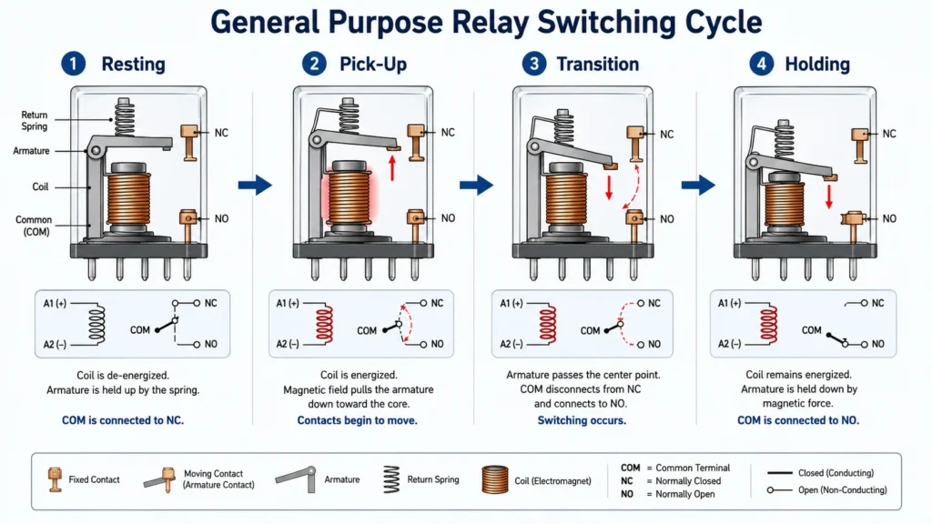
What follows is the full sequence for a relay with both normally open (NO) and normally closed (NC) changeover contacts—the most common general purpose relay configuration.
Resting State (Coil De-Energized)
Before any voltage is applied, the return spring holds the armature away from the core. A small physical air gap separates the armature face from the core pole face. In this state:
The COM (common) terminal is connected to the NC (normally closed) terminal through the moving contact. Current can flow through the NC circuit.
The NO (normally open) terminal is disconnected—its circuit is incomplete.
The coil draws zero current and generates no magnetic field.
Coil Energization: Current Begins to Flow
When the rated control voltage is applied across the coil terminals, current begins to flow through the copper windings. The current does not rise instantly—the coil’s inductance resists the change. During this brief interval:
The current ramps up following an exponential curve determined by the coil’s inductance and DC resistance.
A proportional magnetic field builds around and through the iron core. The flux density in the core increases as current rises.
The armature has not yet moved; the magnetic force is still below the spring’s holding force.
Armature Pick-Up: Magnetic Force Overcomes the Spring
Once the coil current reaches the pick-up voltage threshold, the magnetic attraction force on the armature exceeds the opposing spring force. At this moment:
The armature begins to rotate or slide toward the core, closing the air gap.
As the gap narrows, the magnetic reluctance of the circuit drops sharply, and the attractive force increases non-linearly. This creates a snap-action effect: once motion starts, it accelerates to completion rapidly.
The moving contacts, mechanically linked to the armature, travel with it.
Contact Transition: Switching the Load Circuit
As the armature completes its travel, the moving contacts shift from their resting position to their energized position:
The moving contact breaks away from the NC terminal first. Any current flowing through the NC circuit is interrupted at this instant. If the NC circuit carries an inductive load, a small arc may form briefly as the contacts separate.
After a short travel gap (the “break” distance), the moving contact strikes the NO terminal, completing the NO circuit. This is a “break-before-make” (Form C) sequence: the NC circuit is guaranteed to open before the NO circuit closes, preventing a momentary short between NC and NO paths.
The entire mechanical transition from pick-up to contact closure typically takes 5 to 20 milliseconds, depending on the relay design, coil voltage, and ambient temperature.
Holding State (Coil Energized, Contacts Settled)
Once the armature is fully seated against the core and the contacts are in their new positions, the relay enters its holding state:
The air gap is reduced to near zero, so the magnetic circuit is highly efficient. The coil current—and therefore power consumption—drops to its holding current, which is lower than the pick-up current.
The COM terminal is now connected to the NO terminal. Current flows through the NO circuit.
The relay will remain in this state as long as the coil voltage stays above the drop-out voltage threshold.
The Magnetic Circuit: How the Coil Creates Motion
Understanding the magnetic circuit helps explain why relay operation depends so heavily on coil voltage, air gap, and core material choices.
When current flows through the coil, it produces a magnetomotive force (MMF) proportional to the current multiplied by the number of coil turns. This MMF drives magnetic flux through a closed path: from the core, across the air gap, into the armature, through the yoke, and back to the core.
The air gap is the dominant source of magnetic reluctance in this circuit—air is about 2,000 times more reluctant to conduct magnetic flux than silicon steel. At the start of the switching cycle, with the armature far from the core, most of the MMF is spent overcoming the air gap. This is why a higher current is needed to initiate motion (pick-up) than to hold the armature in place once it is seated.
The core is laminated—built from thin insulated steel sheets rather than a solid block—to suppress eddy currents. Eddy currents are circulating currents induced in the core material by the changing magnetic field. They waste energy as heat and oppose the flux changes that the coil is trying to produce. Lamination forces these currents into narrower paths with higher resistance, dramatically reducing the loss.
How Does a General Purpose Relay Work?
AC Coil vs DC Coil: Two Different Operating Principles
General purpose relays are available with coils rated for either AC or DC supply, and their internal operating physics differ in one critical respect.
DC Coil Operation
A DC coil behaves as a simple inductor plus resistor. Once the magnetic field is fully established and the armature is seated, the current stabilizes at a value determined solely by the coil’s DC resistance: I = V / R. The magnetic flux is steady, and the armature experiences a constant holding force. There is no hum, no vibration, and no shading ring required. The only concern is the inductive voltage spike when the coil is switched off—a topic covered in the de-energization section below.
AC Coil Operation
An AC coil faces a fundamentally different challenge. Because the supply voltage alternates at the line frequency (50 or 60 Hz), the magnetic flux passes through zero twice per cycle—100 or 120 times per second. At each zero crossing, the magnetic force momentarily drops to zero. Without a countermeasure, the armature would chatter against the core at twice the line frequency, producing loud buzzing, contact bounce, and rapid wear.
The solution is a shading ring (also called a shading coil)—a single short-circuited turn of copper or aluminum embedded in a slot on the pole face. The shading ring acts as a shorted secondary winding of a transformer. It creates a secondary magnetic flux that is phase-delayed relative to the main flux. The result is that the net magnetic force on the armature never falls to zero, even when the main flux crosses zero. The armature is held firmly, and the relay operates quietly.
The key engineering consequence: an AC coil and a DC coil are never interchangeable, even if both are labeled “24V.” The AC coil relies on inductive impedance to limit current; if connected to DC, only the coil’s DC resistance limits current, and the coil may overheat or burn out. Conversely, a DC coil on AC may fail to pull in or hold because its magnetic circuit is not designed for alternating flux.
Characteristic
DC Coil
AC Coil
Current-limiting mechanism
DC resistance only
Inductive impedance + DC resistance
Flux characteristic
Steady, unidirectional
Alternating, sinusoidal
Shading ring required?
No
Yes (prevents chatter at zero crossings)
Core lamination
Optional (solid core acceptable)
Mandatory (laminated to suppress eddy currents)
Inrush current
Gradual ramp due to inductance
High initial inrush; limited by impedance once seated
Voltage spike on turn-off
High (inductive kick); diode suppression common
Lower (current may already be near zero at switch-off)
Hum / vibration
None
Low (suppressed by shading ring)
What Happens When the Coil De-Energizes
Removing coil voltage triggers the reverse of the energization sequence, with one important electrical side effect.
When the control circuit opens the coil current path, the current through the inductive coil cannot stop instantly. The collapsing magnetic field induces a back EMF (counter-electromotive force) that tries to maintain current flow. The induced voltage can reach hundreds of volts—many times the original coil voltage—depending on how quickly the circuit is interrupted.
This voltage spike can damage the transistor, MOSFET, or PLC output module that was driving the coil. The standard protection is a flyback diode connected in reverse across the DC coil. During normal operation, the diode is reverse-biased and does nothing. When the coil is switched off, the back EMF forward-biases the diode, which provides a low-resistance path for the inductive current to circulate and dissipate safely as heat in the coil resistance.
For AC coils, an RC snubber (a resistor and capacitor in series across the coil) serves a similar purpose, absorbing the transient energy. Some relays have these suppression components built in, noted as a diode (D) or RC (CR) option in model codes.
Mechanically, the return spring pulls the armature back to its resting position as soon as the magnetic force falls below the spring force. The moving contacts break from NO and reconnect to NC, completing the switching cycle.
Contact Dynamics: Bounce, Arcing, and Material Effects
The mechanical movement of the contacts is not perfectly clean. Two phenomena affect relay life and performance.
Contact Bounce
When the moving contact strikes the fixed contact, it does not simply stop. Like a ball bouncing on a table, it rebounds slightly before settling. During this contact bounce period—lasting a few hundred microseconds to a few milliseconds—the electrical connection makes and breaks several times. For DC loads, this is mostly a nuisance. For high-speed digital circuits, it can produce spurious edges that require debouncing in software or hardware. For AC loads, bounce during peak voltage can cause repeated arcing and accelerated contact wear.
Arcing
When contacts open under load, the current does not stop instantly. Instead, the voltage across the separating contacts ionizes the surrounding air, creating a conductive plasma channel—an arc. The arc sustains current flow until the contact gap is wide enough to extinguish it, or until the AC current naturally crosses zero. Arcing generates intense localized heat that erodes contact material, transfers metal from one contact to the other, and can weld contacts together if the arc energy is high enough.
This is why relay contact life ratings always specify the load conditions. A relay rated for 100,000 operations at 5A resistive may last only 10,000 operations when switching a 5A inductive load—because the arc energy at break is far higher. Silver alloy contacts (AgCdO, AgNi, AgSnO₂) are chosen precisely because they resist arc erosion and welding better than pure silver or copper.
Factors That Affect Relay Operation
Several external conditions can shift the pick-up voltage, drop-out voltage, switching speed, and contact life.
Factor
Effect
Practical Implication
Coil temperature
Copper resistance increases ~0.4% per °C; higher temperature means lower coil current for the same voltage
At high ambient temperature, the relay may fail to pick up if the supply voltage is marginal
Coil voltage variation
Pick-up typically requires 70–80% of rated voltage; drop-out occurs below 10–20%
Long cable runs with voltage drop, or brownout conditions, can cause unexpected drop-out
Load type
Inductive loads create higher arc energy; capacitive loads cause high inrush on contact closure
Derate contact ratings for inductive, capacitive, lamp, and motor loads
Switching frequency
High cycle rates build up heat and accelerate mechanical wear
Check the rated mechanical and electrical life at your operating frequency
Mounting orientation
Gravity and vibration direction affect armature movement and contact force
Follow the manufacturer’s recommended mounting orientation for consistent operation
Ambient contamination
Dust, humidity, and corrosive gases degrade contact surfaces over time
Use sealed or dust-cover enclosures in harsh environments; consider gold-plated contacts for low-level signal switching
Common Failure Modes and Their Root Causes
When a general purpose relay stops working correctly, the root cause can usually be traced to one of the mechanisms described above.
Symptom
Likely Root Cause
Mechanism
Relay does not pick up (no click)
Wrong coil voltage, open coil, or supply below pick-up threshold
Insufficient MMF to overcome the spring force and air gap reluctance
Relay chatters or buzzes loudly
Damaged or missing shading ring (AC coil); supply voltage too low
Magnetic force falls below holding threshold during zero crossings
Contacts stick or weld closed
Excessive inrush current or short-circuit on the load side
Arc heat melts contact material; upon cooling, contacts fuse together
Contacts fail to conduct (open circuit)
Contact erosion, oxidation, or contamination
Arc erosion removes contact material; sulfidation or dust builds a resistive film
Coil burns out
Overvoltage, or DC applied to an AC-rated coil
Excessive current generates I²R heat beyond the coil’s thermal rating
Driver transistor or PLC output fails
Missing flyback diode on a DC coil
Back EMF spike exceeds the semiconductor’s breakdown voltage
The general purpose relay’s working principle is elegant: a small electrical current creates a magnetic field, that field moves a physical armature, and that motion switches one or more independent circuits. The key details—coil type, air gap dynamics, contact materials, bounce, arcing, and suppression—are what separate a reliable installation from a recurring failure. Understanding these details lets you choose the right coil voltage, specify adequate contact ratings, protect your driver circuits, and interpret the relay’s behavior during commissioning and troubleshooting.
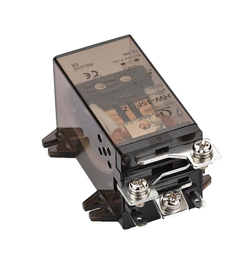
If you are selecting general purpose relays for a control panel, OEM product, or industrial system, browse DPDT and 3PDT models with AC and DC coil options. For help matching a relay to your specific load and operating conditions, contact the HWRELAY engineering team for technical recommendations, datasheets, and samples.
FAQ
How fast does a general purpose relay switch?
Typical pick-up time is 5–20 ms and drop-out time is 3–10 ms for a standard DC-coil general purpose relay. AC-coil relays are slightly slower due to the need for flux to build across multiple half-cycles. Actual timing depends on coil voltage margin, temperature, and whether coil suppression components are installed (a flyback diode slows drop-out).
Why does a DC relay need a flyback diode?
When the coil current is interrupted, the collapsing magnetic field induces a high-voltage spike that can destroy the transistor or PLC output driving the coil. A flyback diode provides a safe path for this inductive energy to dissipate, protecting the upstream electronics.
Can I hear a relay click when it operates?
Yes. The click sound is the armature striking the core (on pick-up) or the armature hitting its backstop (on drop-out). In some applications, this audible feedback is useful for commissioning and troubleshooting. In noise-sensitive environments, a solid-state relay may be preferred since it has no moving parts and operates silently.
What happens if I apply the wrong coil voltage?
Too low a voltage: the relay may not pick up, or it may chatter. Too high a voltage: the coil overheats and may burn out. Applying DC to an AC coil can cause immediate thermal damage because the coil’s DC resistance alone cannot limit current enough. Always match both the voltage value and the AC/DC type.
Does the relay need a minimum load current to work properly?
For silver-alloy contacts switching power-level signals, no. However, for very low-level signals (microamps, millivolts), silver contacts can develop a surface film that increases contact resistance. In such cases, gold-plated contacts or bifurcated (split) contacts are recommended to maintain reliable conduction at low signal levels.
How is a general purpose relay different from a power relay in its working principle?
The fundamental electromagnetic principle is the same. The differences are in scale and construction: a power relay uses a larger coil, heavier contacts, wider contact gaps, and stronger springs to handle higher currents (25A–60A+). It may also incorporate arc chutes or magnetic blowouts to extinguish arcs more aggressively than a general purpose relay requires.
A clear guide covering the definition, working principle, components, contact types, specifications, and selection of general purpose relays for industrial control and automation.
We use cookies to enhance your browsing experience, serve personalised ads or content, and analyse our traffic. By clicking "Accept All", you consent to our use of cookies.
Get a Free Quote
Your email information is completely secure and will not be disclosed to third parties for any reason.
Interested In Our Relay Products?
Get the latest product brochures and technical data.