Power relay switch is the “muscle” of an electrical control system, turning heavy loads on and off safely while your PLC, controller, or IoT module only handles tiny signals. For B2B buyers in industrial automation, HVAC, new energy, telecom, or power distribution, understanding how a power relay switch works, what components matter, and how it differs from other switching devices directly impacts system reliability and lifecycle cost.
What is a power relay switch?
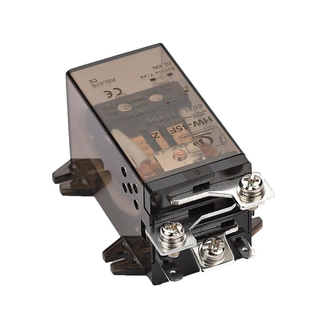
A HW-40F-2Z power relay switch is an electromechanical or solid‑state device that uses a low‑power control signal to open or close a higher‑power circuit. In other words, it behaves like an automatic switch that isolates the control side from the load side while safely handling high voltage or high current.
In many B2B scenarios, power relay switches are used in power distribution panels, building management systems, EV chargers, industrial machines, and smart home hubs where high‑power loads like motors, compressors, heaters, or lighting circuits must be switched frequently and reliably.
In project design specs, power relay switches usually show up with requirements like contact form, coil voltage, switching capacity, insulation distance, and safety approvals. They act as the key element in control cabinets and PCB assemblies where safety, isolation, and compliance with IEC or UL standards are strictly audited.
Aspect
Role of power relay switch
Safety isolation
Separates low‑voltage control (PLC, MCU, IoT) from high‑power load circuits.
Load control
Switches motors, transformers, heaters, and lighting circuits on/off.
Signal amplification
Uses a small coil current to drive a large load current safely.
System integration
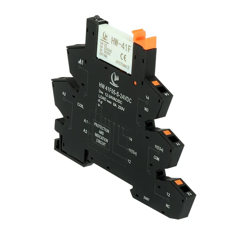
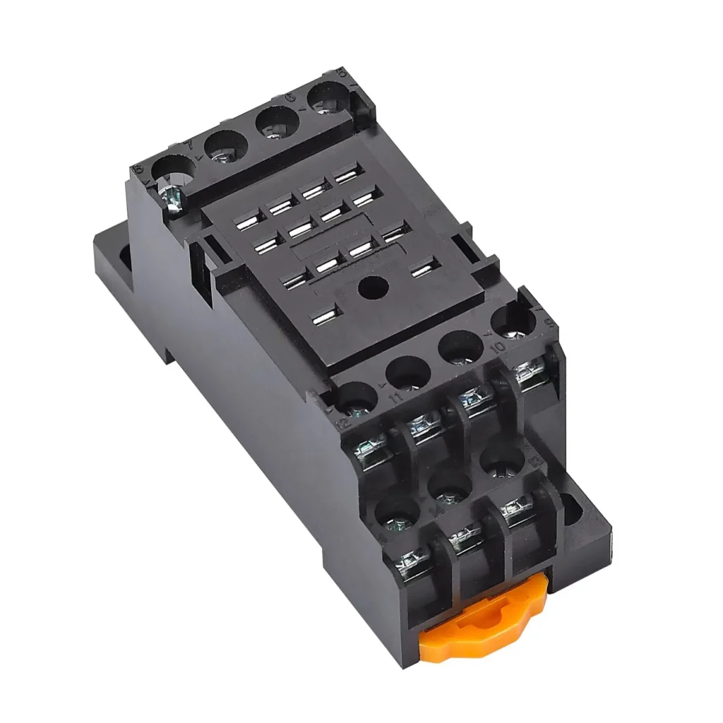
Mounts on PCBs, DIN rails, or sockets in panels and equipment.
If your company needs stable volume supply or custom coil/load ratings, it is often more efficient to talk directly with a power relay switch manufacturer or OEM provider rather than only buying through distributors.
How does a power relay switch work?
Most traditional HW-40F-2Z power relay switches are based on electromagnetic induction: when a voltage is applied to the coil, a magnetic field is generated, pulling a movable armature that changes the state of the contacts. Remove the coil power and the magnetic field collapses, the spring returns the armature, and the contacts revert to their original position.
In simple terms, a power relay switch uses a small control current to mechanically operate a set of contacts in another circuit. This makes it ideal for scenarios where a microcontroller output or PLC I/O cannot directly handle high voltage or inrush current, such as motor start or transformer energizing.
Basic working sequence
Control side (coil) receives DC or AC voltage (for example 5 VDC from a PCB or 230 VAC from a control circuit).
Coil current creates a magnetic field in the iron core and yoke, attracting the armature.
Contacts change state: normally open (NO) contacts close, normally closed (NC) contacts open, or a changeover contact toggles between two outputs.
Load side circuit (e.g. 250 VAC, 16 A) is connected or disconnected accordingly.
When coil power is removed, the spring resets the armature and returns contacts to rest state.
Step
Coil status
Magnetic field
Contact state effect
Idle
De‑energized
None
NO open, NC closed; no load power.
Energized
Voltage applied
Present
NO close, NC open; load is powered.
Released
Voltage removed
Collapsing
Contacts return to idle; load is cut off.
If you are designing an industrial control panel or PCB and want to reduce field failures, selecting the correct coil voltage, contact form and contact rating for your power relay switch is often more important than the controller brand.
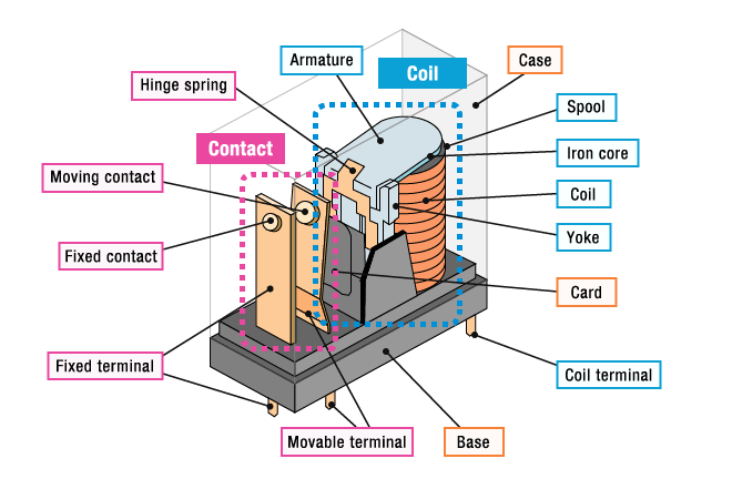
Main components of a power relay
Although different models exist, most electromagnetic power relay switches share a similar internal structure. Understanding each part helps B2B engineers and buyers evaluate quality and performance beyond just the datasheet values.
Core components inside
A typical electromagnetic power relay switch contains:
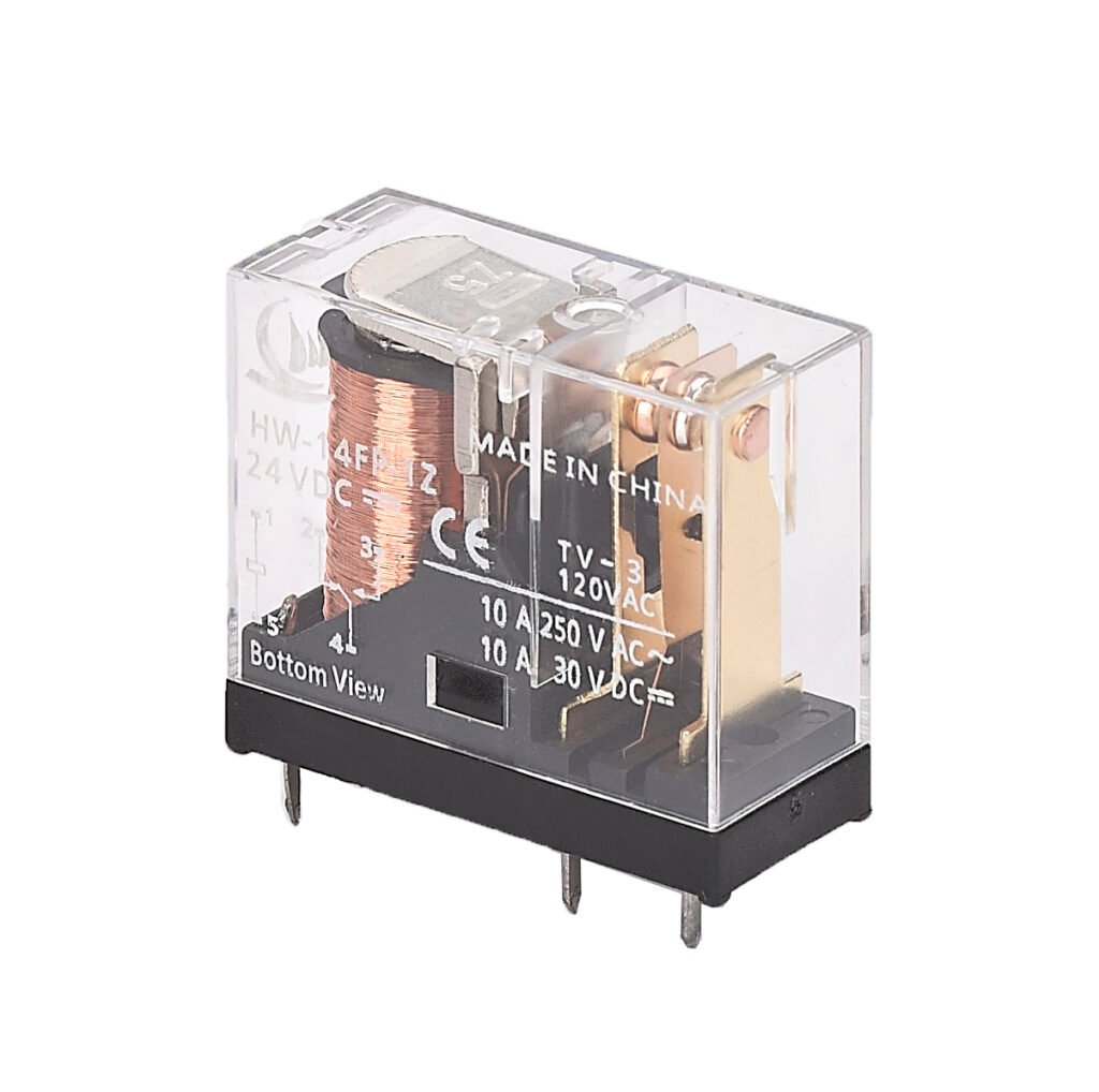
Terminals and housing (sometimes transparent for inspection)
The coil is usually wound from copper wire around an iron core which amplifies the magnetic field. The armature is a movable piece of metal linked mechanically to the contact mechanism and pulled toward the core when the coil is energized.
Component
Function in power relay switch
Coil
Generates magnetic field when energized by control voltage.
Iron core/yoke
Provides a closed magnetic path to improve efficiency.
Armature
Moves to open/close contacts under magnetic force.
Contacts
Conduct or interrupt load current (NO, NC, COM variants).
Spring
Returns armature and contacts to default state when coil off.
Housing/terminals
Provides insulation, mounting and connection interface.
Premium industrial and power relay switch models often add extra elements like arc barriers, contact plating (e.g. silver alloy), and reinforced creepage distances to improve endurance under high inrush or inductive loads. This is critical if your application is motor control, compressor start, or transformer switching, where the first microseconds of connection create very high peaks.
Types of power relay switches
Power relay switches can be classified by several criteria: mechanical vs solid‑state, contact form, latching vs non‑latching, and AC vs DC coil types. Choosing the right type directly affects system safety, response speed, and maintenance cost for B2B projects.
Mechanical vs solid‑state power relay switch
Mechanical power relay use physical contacts moved by an armature, while solid‑state relays (SSR) use semiconductor devices like triacs, thyristors, or MOSFETs triggered through opto‑couplers. Mechanical relays provide full galvanic isolation and visible contact gap, whereas SSRs offer silent, fast switching with no mechanical wear.
Type
Key characteristics
Mechanical power relay switch
Physical contacts, audible click, high surge tolerance, contact wear over life.
Solid‑state relay (SSR)
No moving parts, silent, fast, good for high switching cycles, sensitive to over‑voltage.
Electromagnetic power relay
Typical mechanical relay using coil and armature for actuation.
If your application requires millions of operations per day, such as in fast switching heaters or industrial temperature controllers, an SSR‑type power relay may be more suitable despite higher unit cost.
Contact forms (SPST, SPDT, DPDT, etc.)
From the contact side, a power relay switch can have different “poles” and “throws.” Common options include single‑pole single‑throw (SPST), single‑pole double‑throw (SPDT), double‑pole double‑throw (DPDT), and multi‑pole versions.
SPST‑NO: simple ON/OFF, normally open contact closes when coil is energized.
SPDT (changeover): common terminal switches between NC and NO, widely used for control logic and signal routing.
DPDT: two independent SPDT sections in one housing, allowing control of two circuits simultaneously.
Contact form
Description and common B2B usage
SPST‑NO
Basic load switching in lighting, pumps, fans.
SPDT
Changeover applications, interlocking control, power source selection.
DPDT
Control of two circuits or 2‑phase lines, simple reversing of small DC motors.
In tender documents and BOM lists you will often see these written as “1 Form A”, “1 Form C”, etc., so aligning your engineering notation with the relay manufacturer’s datasheet prevents procurement confusion.
Power relay switch vs contactor vs solid‑state relay
B2B buyers often ask: “Should this project use a power relay, a contactor, or a solid‑state relay?” These three are all switching devices, but they target slightly different power levels and duty cycles.
Generally, power relay switches are used for low to medium power loads on PCB or in compact control modules, while contactors are used in heavy‑duty motor and power distribution systems. Solid‑state relays sit between or alongside these options when silent, high‑frequency switching or fine control is required.
Device type
Typical load level and usage
Power relay switch
Up to tens of amps at low/medium voltage; PCB or modular control.
Contactor
Higher power, large motors, three‑phase circuits, MCC panels.
Solid‑state relay
Fast, silent switching for heaters, LED drivers, precise control.
For example, a “PCB power relay switch” might handle 10–30 A on a board in an EV charger or industrial controller, while a 3‑pole contactor handles 75 A in a motor control center. When planning a new product line, many OEMs combine both: using power relay inside sub‑modules and contactors at the main power distribution layer.
Contact us for custom high-performancepower relays solutions HW-40F-2Z tailored to your needs.
When your engineering team prepares a specification for a power relay switch, it is critical to define more than just the current rating. Many product failures come from underestimating inrush current, ambient temperature, or the nature of the load (resistive vs inductive).
Key specification parameters
Important parameters include:
Coil voltage and type (AC or DC, nominal value, operating range)
Insulation resistance, dielectric strength, creepage and clearance distances
Mounting style (PCB, plug‑in socket, DIN rail module)
Parameter
Why it matters for B2B buyers
Coil voltage
Must match PLC/MCU or control supply to ensure reliable pick‑up.
Contact rating
Protects against overheating and welding under real load conditions.
Electrical life
Affects maintenance cycles and warranty periods.
Insulation specs
Compliance with safety standards and EMC requirements.
During procurement, aligning your purchasing description with these technical parameters allows suppliers to respond faster with compatible power relay switch models and accurate quotations.
Where are power relay switches used?
Across industries, power relay switches appear in many control and protection functions. From simple on/off control to complex automation, they are often hidden inside panels but are vital for uptime and safety.
Common B2B application areas include lighting control systems, telecom equipment, industrial process control, power transmission and distribution protection, and automotive starter solenoids. More recently, they are also widely integrated into smart power relays and IoT‑enabled switching modules for remote monitoring and energy management.
Protection relays, distributed energy resources switching.
Telecom & IT
Power supply switching, backup battery connection.
If your company is planning a new control panel or smart energy meter project, early communication with a power relay switch supplier about expected volumes, certifications, and testing requirements can significantly reduce time to market.
Benefits of using power relay switches for B2B projects
For OEMs, system integrators, and panel builders, the right power relay switch delivers both technical and commercial benefits. It directly impacts reliability, total cost of ownership, and ease of maintenance throughout the lifecycle of the equipment.
From a technical point of view, power relay switches provide safe isolation, flexible control, and the ability to handle a wide range of loads (resistive, inductive, capacitive) with appropriate selection. Commercially, standardized form factors and widely available models help keep component cost and logistics manageable, especially when designing for multi‑market exports.
Benefit
Impact on B2B users
Safety & compliance
Easier certification under IEC/UL standards.
Design flexibility
Supports many voltage and load combinations.
Maintainability
Field‑replaceable modules reduce downtime and service cost.
If you are considering long‑term partnerships, many power relay switch manufacturers also offer custom labeling, packaging, and stocking strategies to support your global supply chain.
How to choose the right power relay switch
For B2B engineers, the selection process involves both electrical and mechanical considerations. Rather than just matching the nominal current, it is important to consider the real operating conditions and regulatory environment of the final equipment.
Use models rated specifically for inductive or motor loads if applicable.
Duty cycle
High switching counts may need SSR or heavy‑duty contacts.
Environment
Consider humidity, contamination level, and mounting orientation.
If you share your detailed application parameters (load, environment, expected lifetime), a specialized power relay switch supplier can usually recommend a standard or customized solution together with life‑test data.
If your company is currently sourcing or designing around HW-40F-2Z power relay switch and you need help choosing models, optimizing BOM cost, or customizing ratings for your market, you can send your detailed application requirements and volume plan to get a targeted quotation and technical proposal.
FAQ
What is the difference between a power relay switch and a contactor?
A power relay switch is typically smaller, with lower current ratings, and often PCB‑mount or modular for control systems, while a contactor is larger, designed for high‑power three‑phase motors and heavy industrial loads. Contactors often include auxiliary contacts and accessories like overload relays, while power relay switches focus on compact and cost‑effective load control.
Can a power relay switch control AC and DC loads?
Yes, many power relay switches are rated for both AC and DC loads, but the contact ratings and maximum switching capacity may differ between AC and DC. Always check the datasheet for separate AC and DC ratings to avoid overheating or contact welding.
How long does a power relay switch last?
Mechanical power relay switches typically specify mechanical life in millions of operations and electrical life in hundreds of thousands to millions, depending on load type and switching conditions. Actual lifetime in the field will depend heavily on the real load, ambient environment, and switching frequency
When should a solid‑state power relay be used instead of a mechanical one?
Solid‑state power relays are preferred when silent operation, very high switching frequency, or very long electrical life with low maintenance is required. They are often used in precise temperature control, fast cycling heaters, and applications sensitive to contact bounce.
How do I know which coil voltage to choose?
The coil voltage should match the available control voltage from your PLC, microcontroller, or auxiliary power supply, with some margin allowed by the relay’s operating range. For example, 24 VDC coils are very common in industrial automation, while 12 VDC and 5 VDC are common in automotive and PCB designs.
Relay symbols are the cornerstone of electrical engineering, the universal language for designing, troubleshooting, and maintaining electrical systems. Whether you’re drawing a residential circuit or a complex industrial control panel, understanding these symbols ensures clarity and accuracy. This article will take you through relay symbols, covering their definitions, components, types, and global standards. By the […]
Industrial automation Miniature relay is transforming manufacturing at an unprecedented pace. Factories increasingly rely on automated systems to boost efficiency, ensure product quality, and reduce labor costs. In this landscape, relays act as the “switching brain” of control systems, playing a vital role that is often underestimated. You might wonder, “Aren’t relays just basic electronic […]
What is a Relay? Hangwang Electrical HW-14F-1Z Relay is an electric switch, Understanding Relay & Wiring Diagrams, used to control the flow of current in a circuit. It uses a small electrical input to manage a larger electrical load, making it a crucial component in various applications. Relays are commonly found in household appliances, industrial […]
We use cookies to enhance your browsing experience, serve personalised ads or content, and analyse our traffic. By clicking "Accept All", you consent to our use of cookies.
Get a Free Quote
Your email information is completely secure and will not be disclosed to third parties for any reason.
Interested In Our Relay Products?
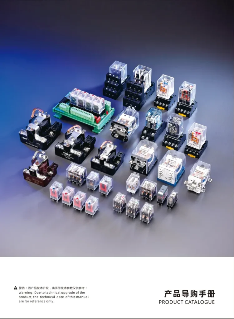
Get the latest product brochures and technical data.