There are several common failure modes for a PCM power relay in automotive and industrial control systems, and most of them can be avoided with the right design, selection, and maintenance strategy. For B2B buyers and engineers, understanding these root causes is the key to preventing unexpected downtime, warranty claims, and costly field returns.
What Is a PCM Power Relay?
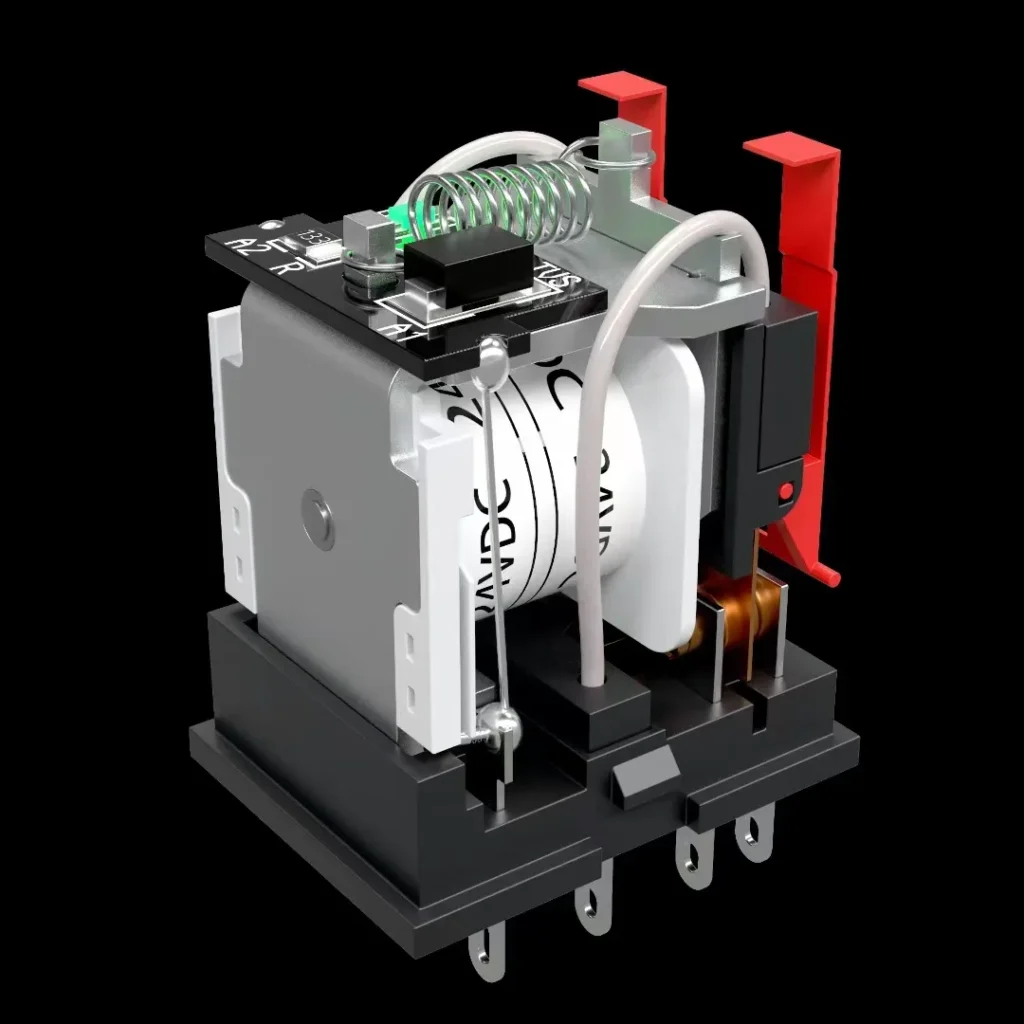
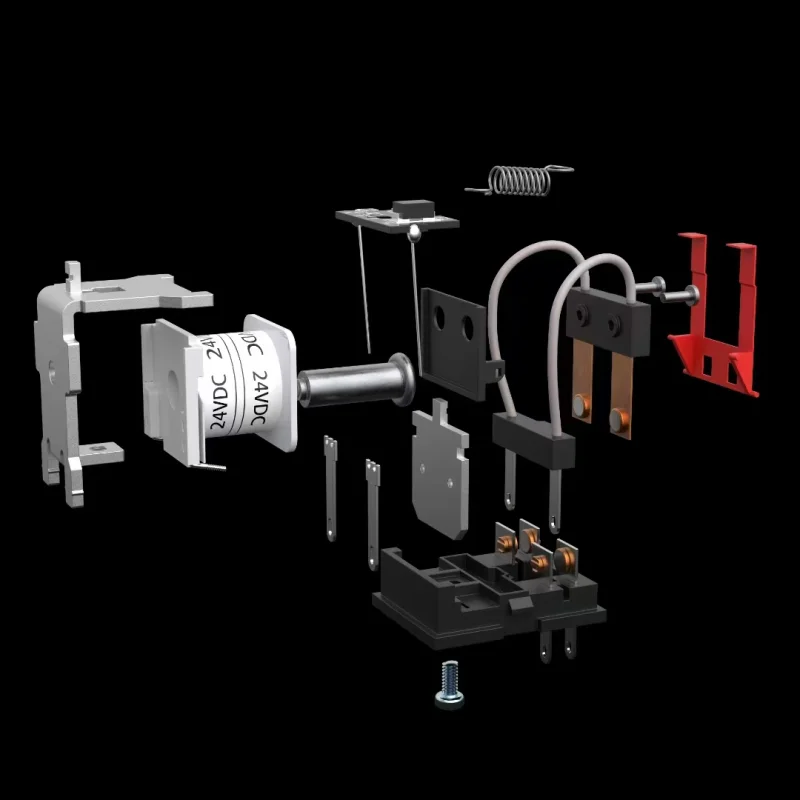
In many automotive and industrial applications, the PCM power relay (sometimes called “PCM relay”, “powertrain control module relay” or just “engine control relay”) is the main switching device that powers the control unit and its peripheral loads. It connects the battery or ignition power to the PCM and other electronics and must handle frequent switching, inrush current and harsh environments.
When this small component fails, symptoms can be dramatic: engine no-start, intermittent stalling, communication loss on CAN bus, or random DTCs. For OEMs and procurement teams, a single weak PCM relay design can impact thousands of vehicles or devices in the field.
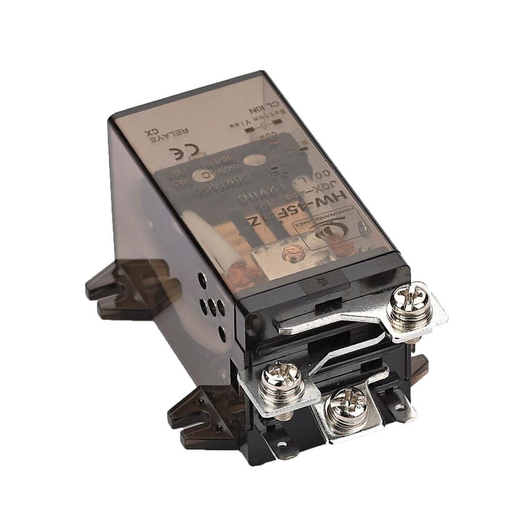
One of the most frequent reasons for HW-38F-3Z PCM power relay failure is electrical overload at the contacts. When the relay is specified close to its limit, or the load changes over time (for example, added sensors, pumps, or fans on the same circuit), the relay may be forced to switch higher current than originally designed. Over time this leads to:
Contact welding due to strong arcing during switching.
Severe contact erosion and pitting from repeated high inrush current.
Carbonization and increased contact resistance, causing heat rise and intermittent faults.
For buyers and design engineers, the key is to treat the PCM power relay as a strategic component in the power distribution architecture, not just a commodity part. Always evaluate:
Steady‑state current.
Inrush or peak current of inductive and capacitive loads.
Switching frequency under real driving or operating conditions.
Typical overload failure patterns
In the field, overloaded PCM HW-38F-3Z power relays often show:
Relay works when cold, fails after warm‑up due to thermal expansion.
Occasional engine cut‑off when multiple loads start at the same time.
Visible melting or discoloration on the relay housing or socket.
If you are an OEM or tier‑1 supplier, this is also where design validation and HALT/HASS testing should focus. Intentionally test worst‑case scenarios: low voltage cranking, high temperature, maximum load, and rapid cycling. Ask your relay vendor for load curve data and contact endurance curves under inductive load, not only resistive load.
If you are currently evaluating PCM power relay suppliers and want support on derating and load matching, feel free to send your spec sheet and typical load profile to our engineering team for a quick application review.
2. Voltage Spikes, Transients and Poor Suppression
Another major category of PCM relay failure is related to voltage transients in the vehicle or equipment power system. Every time an inductive load is switched (solenoids, motors, pumps), the system can generate high‑voltage spikes that stress the relay contacts and insulation.
Without proper transient suppression:
Contacts experience stronger arcing during opening.
Insulation materials age faster.
The coil driver circuit in the PCM itself can be damaged.
Engineers should check:
Whether the relay coil is equipped with a flyback diode, resistor, or TVS.
Whether external inductive loads have snubber circuits.
The actual transient voltage levels on the PCB during EMC testing.
For B‑side customers integrating a PCM power relay in custom ECUs or power distribution modules, working closely with the relay manufacturer’s application team is critical. They can recommend proper suppression networks and share standard reference designs.
3. Thermal Stress and Insufficient Heat Management
Heat is one of the silent killers of PCM power relays. High ambient temperature under the hood or inside compact control boxes, combined with:
Continuous high current.
High contact resistance due to aging.
Poor ventilation and PCB layout.
can cause excessive temperature rise inside the relay. This leads to:
Soften or deformation of plastic housing.
Coil resistance changes and loss of pull‑in margin.
Accelerated oxidation of contacts and springs.
For automotive and industrial B2B users, it is important to treat the PCM relay as part of the overall thermal design. Do not only check “maximum ambient temperature” in the datasheet; instead evaluate:
Temperature rise at specified load, measured on real PCB.
Neighboring components (MOSFETs, shunts, power resistors) that may heat the relay.
Airflow and barrier placement in the power distribution box.
One useful approach is to place temperature sensors near the PCM relay in early prototypes, record thermal behavior under long‑duration endurance tests, and then adjust the relay rating and layout. Procurement teams should ask suppliers for detailed derating curves versus temperature.
If your current PCM power relay is often operating near its thermal limit, switching to a higher current rating or a relay with lower contact resistance can greatly improve service life.
Contact us for custom high-performancepower relays solutions tailored to your needs.
PCM relays in vehicles and mobile equipment have to survive vibration, shock, and mechanical stress over many years. Mechanical issues include:
Armature or spring fatigue, leading to delayed or incomplete closing.
Contact misalignment due to repeated shock.
Housing cracks or micro‑gaps that allow moisture ingress.
In some extreme cases, poor mechanical robustness can cause intermittent failures that are very difficult to reproduce in the lab. To avoid this, engineers and sourcing managers should:
Specify automotive or industrial‑grade PCM power relays with vibration and shock test reports.
Verify that the relay uses secure internal structure and reliable welds.
Ensure proper mounting orientation and mechanical fixation on the PCB or in the fuse box.
If your application is off‑road, construction, or heavy‑duty, consider relays with reinforced housing and higher vibration ratings. In these applications, using consumer‑grade relays just to save a few cents per unit often leads to costly field service later.
5. Environmental Factors: Moisture, Corrosion and Contamination
Environmental exposure is another frequent cause of PCM power relay failure. Even in sealed relays, water vapor, condensation and aggressive chemicals can find their way in over time. Typical issues include:
Contact corrosion, especially in regions with high humidity and salt.
Dust and particles entering through micro‑gaps, leading to blocked movement or increased contact resistance.
Chemical attack on plastic housing or coating from cleaning agents, fuels or oils.
For OEMs selling vehicles or equipment to global markets, relay selection should consider:
Chemical exposure in the engine bay or industrial cabinet.
Choosing sealed or flux‑tight PCM relays, using corrosion‑resistant contact materials, and applying conformal coating on the PCB around the relay can significantly increase reliability. For B2B buyers, it is recommended to ask for salt‑spray and humidity test data before final approval.
If you are dealing with recurring field failures in coastal or industrial environments, upgrading to a sealed PCM power relay or improving enclosure sealing can be a quick and effective solution.
6. Coil Circuit Problems: Under‑voltage, Over‑voltage and Driver Issues
Even if the relay itself is robust, coil drive problems can cause functional failure:
Under‑voltage: The coil does not generate enough force to pull in contacts, especially at low temperatures or with aging.
Over‑voltage: The coil overheats and eventually burns out, causing permanent open circuit.
Ripple and noise: Unstable supply or driver design can cause chatter, which accelerates contact wear.
For engineers, these issues are often related to overall power system design rather than the relay alone. Focus on:
Ensuring the PCM power relay coil is driven within its specified voltage range across the full operating temperature and battery range.
Checking wire harness voltage drop, especially during cranking or heavy load.
Verifying the driver transistor or low‑side driver is properly sized and protected.
If your system uses PWM or special drive schemes, validate them with the relay manufacturer. Not all PCM power relays are designed for non‑DC coil drive, and some may suffer from noise or vibration if mis‑driven.
7. Design and Selection Mistakes at the Sourcing Stage
From a procurement point of view, many PCM power relay failures can be traced back to selection mistakes at the early project stage:
Choosing relays based only on price, without reviewing detailed technical data.
Using a general‑purpose power relay instead of a relay specifically rated for engine/PCM loads.
Ignoring certification and automotive qualification (such as relevant AEC standards).
To avoid this, B‑side purchasers and project engineers should set up a structured relay sourcing process:
Define exact load type and duty cycle for the PCM power relay.
Request detailed data sheets, load curves, and reliability reports.
Conduct small‑batch pilot tests in real vehicles or equipment.
Collect field data and adjust specification before mass production.
A reliable relay partner will provide technical support, custom testing and even co‑design the PCB layout. If you are starting a new ECU or power distribution module project, reaching out early to discuss PCM power relay options can prevent redesigns later.
8. Preventive Measures for Long‑Life PCM Power Relays
Now that we have covered the common failure causes, what can engineers and purchasing teams actually do to prevent PCM power relay failures?
Key preventive measures include:
Proper derating: Select a current rating with sufficient margin, considering peak and inrush, as well as temperature.
Good PCB layout: Ensure short, wide traces for high‑current paths and minimize hotspots around the relay.
Transient protection: Use appropriate suppression for coils and inductive loads.
Environmental protection: Choose sealed relays and good enclosure design in harsh conditions.
Quality assurance: Audit suppliers, review test reports, and run incoming inspection programs.
For large B2B buyers, implementing supplier audits and PPAP‑like processes for key components such as PCM power relays is worthwhile. It ensures traceability and consistent quality batch‑to‑batch.
If you are under pressure to reduce warranty failures or improve MTBF, consider running a joint reliability workshop with your relay vendor. Real field failure data, combined with design insights, often reveals simple improvements.
9. How to Diagnose PCM Power Relay Issues in the Field
For engineers, service teams, and even technically inclined buyers, being able to quickly judge whether the PCM power relay is the root cause of a failure is very valuable.
Typical diagnostic steps include:
Listening and measurement: Check if the relay “clicks” when the ignition is turned on, and measure voltage at the output terminal.
Temperature check: Inspect for overheating or discoloration on the relay and socket.
Swap test: Temporarily replace the suspect PCM relay with a known good relay of the same type.
Visual inspection: After removal, inspect for cracks, corrosion, or burn marks.
For fleet customers and industrial end‑users, establishing a simple relay diagnostic procedure can reduce unnecessary module replacements and shorten downtime. Procurement teams can then use feedback from service centers to refine the approved parts list for PCM relays.
If you would like an application‑specific test checklist or standard operating procedure for PCM power relay diagnostics, share your platform type (light vehicle, bus, construction machinery, industrial equipment) and the voltage level, and a tailored guide can be prepared.
FAQ
What is a PCM power relay used for?
A PCM power relay supplies power to the powertrain control module and related circuits, acting as the main electronic “switch” between the battery/ignition and the control system.
How long does a PCM power relay typically last?
In a properly designed system with correct derating and protection, the relay can last the lifetime of the vehicle or device; however, overload, heat, and harsh environments can significantly shorten service life.
Can a failing PCM power relay cause intermittent engine stall or no‑start?
Yes. A worn or overheated PCM power relay can cause intermittent power loss to the PCM, leading to random stalling, no‑start, and diagnostic trouble codes that are difficult to reproduce.
What should B2B buyers look for when sourcing PCM power relays?
Focus on current rating with margin, automotive or industrial qualification, environmental sealing, proven field performance, and strong technical support from the manufacturer rather than just unit price.
How can I reduce PCM power relay failures in my platform?
When a vehicle refuses to start and diagnostics point to the “PCM power relay,” that small component suddenly becomes very important to engineers, buyers, and maintenance teams. For OEMs, wholesalers, and parts procurement, understanding what a PCM power relay does – and how to choose the right one – directly affects reliability, warranty cost, and […]
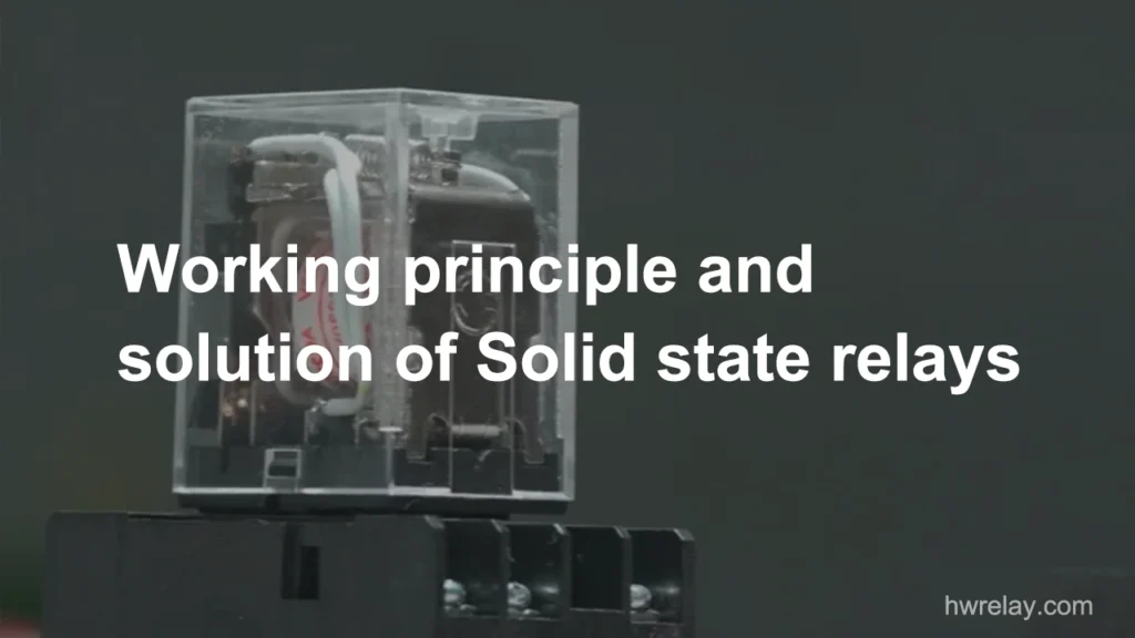
Solid state relays (SSRs) are crucial components in switching circuits, but they can encounter issues. This guide will help you understand, identify, and resolve common SSR problems, ensuring your equipment operates smoothly. What is a Solid state relays and How it Works? Solid state relays are electronic switches that use semiconductors to control circuits based […]
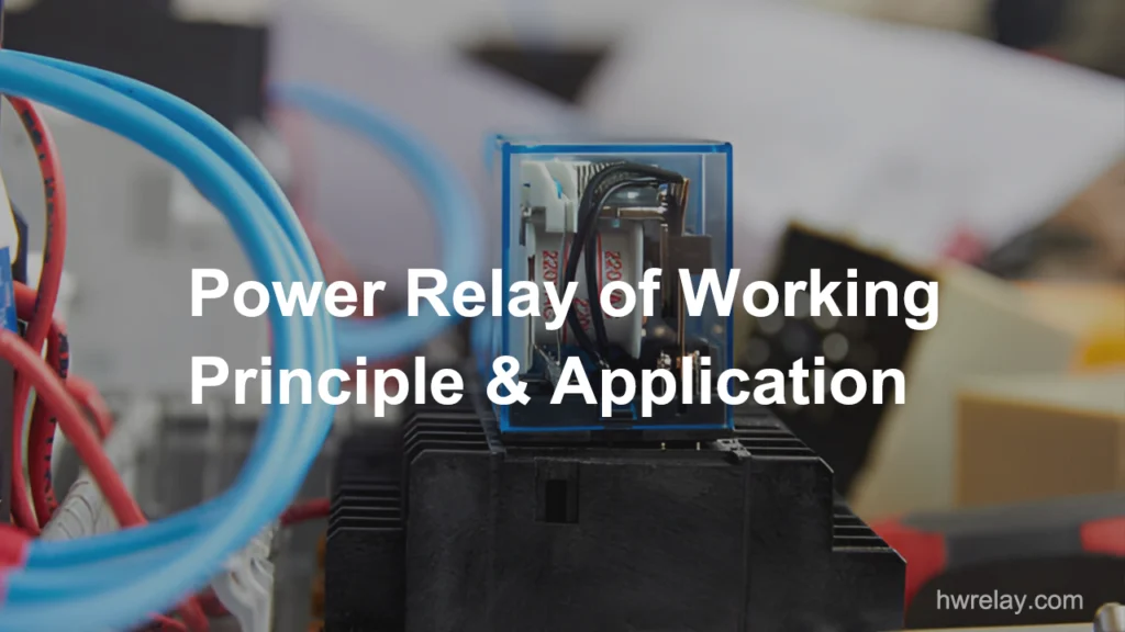
Have you ever wondered what kind of “switch” behind large and complex industrial equipment makes motors start smoothly and machines stop safely? The answer is the power relay. Although power relays seem inconspicuous, they play a critical role in ensuring industrial automation systems run smoothly and efficiently. In this article, we will take you deep […]
We use cookies to enhance your browsing experience, serve personalised ads or content, and analyse our traffic. By clicking "Accept All", you consent to our use of cookies.
Get a Free Quote
Your email information is completely secure and will not be disclosed to third parties for any reason.
Interested In Our Relay Products?
Get the latest product brochures and technical data.