In this article, I’m going to walk you through one of the most practical workhorses in industrial control panels: the Power Relay power control module relay family that includes the HW‑30F‑2Z. You’ll get clear wiring guidance, selection rules, and real‑world tips that you can actually plug into your next project. If you’ve ever stared at an 8‑pin relay block and thought, “What goes where?”—you’re in the right place.
I’m writing this as a transformer and power‑relay specialist who talks to purchasing managers and system integrators every day. So we’ll skip fluffy theory and focus on how to wire it, how to pick the right version, and which model fits your load profile.
What a power control module relay actually does
A power control module relay is, at its core, an electromagnetic switch that lets you control a relatively high‑power circuit using a small, low‑power signal. The relay coil receives a control voltage (for example 12 VDC, 24 VDC, or 220 VAC), and the contacts then switch a load that can be much larger—typically tens of amperes at 250 VAC or lower DC voltages.
This kind of relay is especially useful when you have:
A PLC or microcontroller with limited output current.
A contactor, motor, heater, or lighting circuit that draws multiple amperes.
A need to electrically isolate the control side from the power side for safety and noise reduction.
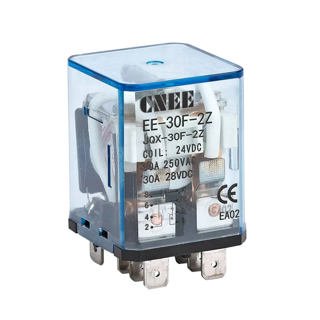
In our case, the HW‑30F‑2Z sits in the “high‑power industrial relay” bracket, rated up to 30 A at 250 VAC or 28 VDC per contact, with a DPDT (double pole double throw) configuration. That means it can handle two separate load paths, each with a normally open and normally closed contact, giving you a lot of routing flexibility inside control panels.
If you’re familiar with the JQX‑30F family, you’ll recognize that the HW‑30F‑2Z is a compatible or derivative high‑power relay in the same footprint and contact class. The 30 A rating per contact makes it suitable for:
Small contactors and motor‑starter circuits.
Large‑capacity heating elements in ovens or HVAC equipment.
Industrial lighting and auxiliary power circuits.
A key advantage is contact material and life. The JQX‑30F series uses silver‑based alloy contacts (often AgCdO or AgSnO₂) with low contact resistance and good arc resistance. This directly translates to:
Longer electrical life (typically tens of thousands of operations).
Lower contact resistance (around ≤100 mΩ at 1 A).
Better reliability when switching inductive loads like motors or transformers.
From a procurement perspective, this kind of high‑power relay module is a sweet spot: more robust than generic 10 A PCB relays, yet still cost‑effective and compact enough for standard DIN‑rail or panel‑mount layouts.
How to wire a power control module relay (HW‑30F‑2Z style)
Let’s get concrete: suppose you’re installing a power control module relay like the HW‑30F‑2Z into a control panel that switches a 230 VAC heater bank. Here’s how you’d approach the wiring in a way that’s both safe and easy to troubleshoot.
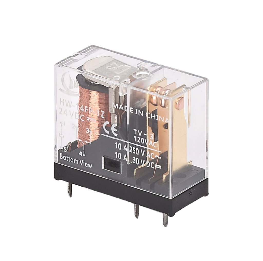
Basic pin‑out and labeling
Most 8‑pin high‑power relays in this class follow an IEC‑style layout with:
Two coil terminals (A1 and A2) for your control voltage.
Four contact terminals arranged as two DPDT channels (COM1, NO1, NC1 and COM2, NO2, NC2).
If you unwrap the spec‑style language, it means:
When the coil is de‑energized:
Current flows through the NC (normally closed) contacts.
NO (normally open) contacts are off.
When you energize the coil:
The relay “flips,” breaking the NC side and making the NO side.
In a 2‑channel (2Z) relay, you can use each pole independently or in parallel for higher current.
A practical wiring tip: always wire the load through the NO if you want the device to start when the control signal is present. This matches the “fail‑safe” logic used in most industrial panels.
Step‑by‑step wiring example
Let’s say you’re using a 24 VDC PLC output to control a 230 VAC 2 kW heater through an HW‑30F‑2Z‑style relay:
Control side (coil):
Connect A1 to the 24 VDC supply.
Connect A2 to the PLC “relay output” terminal that will be controlled by your program.
Ensure the PLC output can handle the coil current (typically a few tens of milliamps for 24 VDC, or a bit higher for 110/220 VAC coils).
Load side (contacts):
Route the 230 VAC live line to COM1 and COM2.
Connect the NO1 and NO2 terminals to the heater input.
Return the neutral/slave side of the heater to the neutral/grounded conductor.
If your load is big enough, you can parallel the two poles (COM1–NO1 and COM2–NO2) to distribute the current, but only if your relay data sheet explicitly allows it.
Protection and grounding:
Add a small fuse or circuit breaker on the 230 VAC line side.
If you expect inductive spikes (motors, contactor coils), consider a flyback diode across the PLC output or an RC snubber across the relay contacts.
This kind of layout is where a DPDT intermediate relay shines: you can route power, status signals, and even diagnostics over the same module without needing extra relays.
Table: Typical wiring roles for HW‑30F‑2Z–style relay
Pin group
What it does
Typical user example
A1, A2
Coil supply (control voltage)
24 VDC PLC output
COM1, COM2
Common terminals for each pole
Live 230 VAC line
NO1, NO2
Normally open contacts
Outputs to heater or contactor
NC1, NC2
Normally closed contacts
Alarm or backup circuit
If you’re not sure which pin is which, many manufacturers provide a small legend right on the relay body or in the datasheet. As a rule of thumb, the center row is usually contacts, and the outer row is the coil.
Contact us for custom HW‑30F‑2Z power relays solutions tailored to your needs.
How to choose the right power control module relay
When I talk to procurement and engineering teams, the usual questions are: “Which rating do we need?” and “Should we go for 12 V, 24 V, 110 V, or 220 V control?” Let’s turn that into a practical checklist.
1. Match the load current and voltage
For a power control module relay like the HW‑30F‑2Z, the basic rule is:
The relay contact rating must be equal to or higher than the maximum load current.
For inductive loads (motors, contactors), many manufacturers derate the current slightly and recommend an extra margin (10–20%).
In practice, if your heater draws 8 A at 230 VAC, a 30 A relay is more than enough. But if you’re switching a 25 A motor starting current, you should still be fine, as long as the relay’s inrush current spec allows it.
2. Decide on coil voltage
Modern high‑power relay modules often support multiple coil voltages (6, 12, 24, 48, 110, 220 VAC/DC). The choice depends on:
What your control system already uses (most industrial PLCs supply 24 VDC).
Whether you want to avoid extra power supplies.
How much coil current your PLC outputs can handle.
If you’re designing a new panel, 24 VDC is usually the safest, most flexible choice. For legacy or HVAC systems, 110 VAC or 220 VAC coils can make sense, but they do draw more current and may require bulkier control wiring.
A 24 VDC power control module relay integrates easily with modern PLC‑based control panels. This power control module relay is ideal for high‑power relay modules for PLC outputs, where each 24 VDC channel switches a 230 VAC load safely.
3. Check contact configuration
The HW‑30F‑2Z is a DPDT (2Z) relay, meaning you have two poles, each with NO and NC contacts. If your project needs:
Only simple ON/OFF switching: use one pole.
Redundant or backup paths: use both poles.
Logic inversion (e.g., “trouble” signal when the relay is off): use the NC contacts.
If you rarely use the NC side, you might consider a SPDT (single pole double throw) version, which is cheaper and takes up the same footprint. But if you expect to need more logic flexibility later, the DPDT module is the safer long‑term buy. The DPDT intermediate relay for industrial panels lets you route power, alarms, and diagnostics from a single module.
Table: Choosing coil voltage vs application
Application
Typical control voltage
Why this works
Industrial automation with PLC
24 VDC
Standard, low power, easy to source
Older HVAC control panels
110 VAC
Matches existing 110 VAC control circuits
Building power systems
220 VAC
Avoids extra DC power supply
Battery or DC‑only systems
12 VDC
Matches 12 V vehicle or backup systems
If you’re unsure, send your full load profile and control‑voltage constraints to your supplier; they can often recommend a specific HW‑30F‑2Z variant (JQX‑30F‑2Z, 24 VDC, 220 VAC, etc.) that fits your cabinet.
How to tell if you should buy HW‑30F‑2Z or an alternative
Once you’ve decided on specs, the next question is: “Should I buy the HW‑30F‑2Z or a different model?” Here’s how I guide customers:
Stick with HW‑30F‑2Z if:
You need up to 30 A at 250 VAC or 28 VDC per contact.
You want a DPDT configuration with two independent poles.
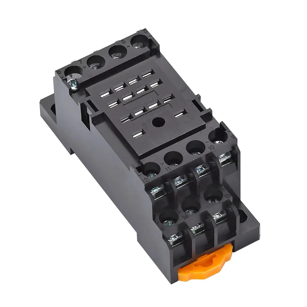
Your panel is already using 8‑pin sockets (FRS01 type or similar).
You’re ordering in volume and want a known, cost‑effective standard module.
Look at alternatives if:
Your load is well below 10 A, and you want a smaller PCB or low‑current relay.
You need a solid‑state relay module with zero mechanical wear (for very high‑cycle applications).
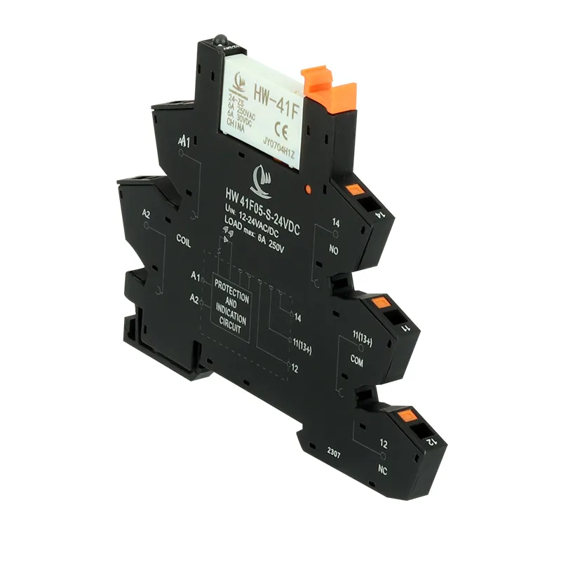
You need a different form factor (DIN‑rail‑mount relay module, multifunction time delay module, etc.).
For many B2B buyers, the HW‑30F‑2Z power control module relay becomes a “go‑to” intermediate relay because it balances performance, size, and price. If that matches your project, it’s worth locking in a preferred part number with your procurement team.
If you’re evaluating a Power Relay power control module relay for your next industrial or HVAC project, the HW‑30F‑2Z is a solid, widely supported option that fits common PLC‑driven panels and 30 A power circuits. With the right wiring and coil‑voltage choice, it can save you cabinet space, reduce spare‑part complexity, and boost long‑term reliability.
If you’d like, you can drop your exact load specs (voltage, current, inductive vs resistive) and control‑voltage environment, and I can help you nail down whether this high‑power relay module is the right fit for your project—or point you toward a slightly different variant.
How do I test if this power control module relay is working?
Apply the rated coil voltage and check continuity from COM to NO or NC using a multimeter. You should see continuity change cleanly when the coil is energized and de‑energized. If the contacts show high resistance or no change, the relay may be worn or damaged.
Can I use this relay for both AC and DC loads?
Yes, many 30 A power relays for HVAC systems and industrial panels support both AC and DC loads, but always check the exact rating (for example 30 A at 250 VAC and 28 VDC). DC loads are harder on contacts due to arcing, so in demanding applications, you may want to derate current slightly or add a snubber.
What is the expected life of this kind of relay?
Typical mechanical life for this class is around 100,000 operations or more, with electrical life often in the tens of thousands of cycles depending on load and switching frequency. For high‑cycle applications (e.g., daily cycling of a heater), consider a higher‑end or solid‑state relay.
Can I parallel the two poles to get more current?
In many cases, yes, but only if the datasheet explicitly allows it. Parallel poles can help share the current between both contact sets, but you must ensure contacts operate and release simultaneously, otherwise one may carry most of the load and wear out faster.
There are several common failure modes for a PCM power relay in automotive and industrial control systems, and most of them can be avoided with the right design, selection, and maintenance strategy.
Industrial automation Miniature relay is transforming manufacturing at an unprecedented pace. Factories increasingly rely on automated systems to boost efficiency, ensure product quality, and reduce labor costs. In this landscape, relays act as the “switching brain” of control systems, playing a vital role that is often underestimated. You might wonder, “Aren’t relays just basic electronic […]
Power relay switch is the “muscle” of an electrical control system, turning heavy loads on and off safely while your PLC, controller, or IoT module only handles tiny signals. For B2B buyers in industrial automation, HVAC, new energy, telecom, or power distribution, understanding how a power relay switch works, what components matter, and how it […]
We use cookies to enhance your browsing experience, serve personalised ads or content, and analyse our traffic. By clicking "Accept All", you consent to our use of cookies.
Get a Free Quote
Your email information is completely secure and will not be disclosed to third parties for any reason.
Interested In Our Relay Products?
Get the latest product brochures and technical data.