Relay Blog
Power Relay Manufacturer for OEM and Industrial Use
Learn how to evaluate a power relay manufacturer, compare relay types, understand pricing factors, and choose the right relay for OEM, export, and industrial sourcing projects.
Read More
Choosing the right coil voltage for a power relay switch can feel tricky, especially when you are designing industrial control panels, OEM equipment, or automation systems for demanding B2B projects. You not only need the relay to pull in reliably, you also have to think about supply tolerance, safety, heat, and long‑term reliability. This guide walks through how coil voltage works, which options are common in industrial power relay switches, and how to select the best value for your application—without over‑engineering or risking failures in the field.
If you are sourcing power relay switches in volume and want tailored coil voltage options (for example 12 VDC, 24 VDC, 110 VAC, 230 VAC), you can always send an enquiry with your load data and control voltage, and an engineer can recommend suitable SKUs quickly.
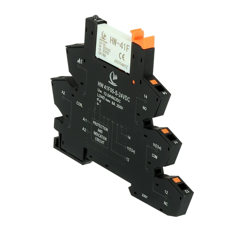
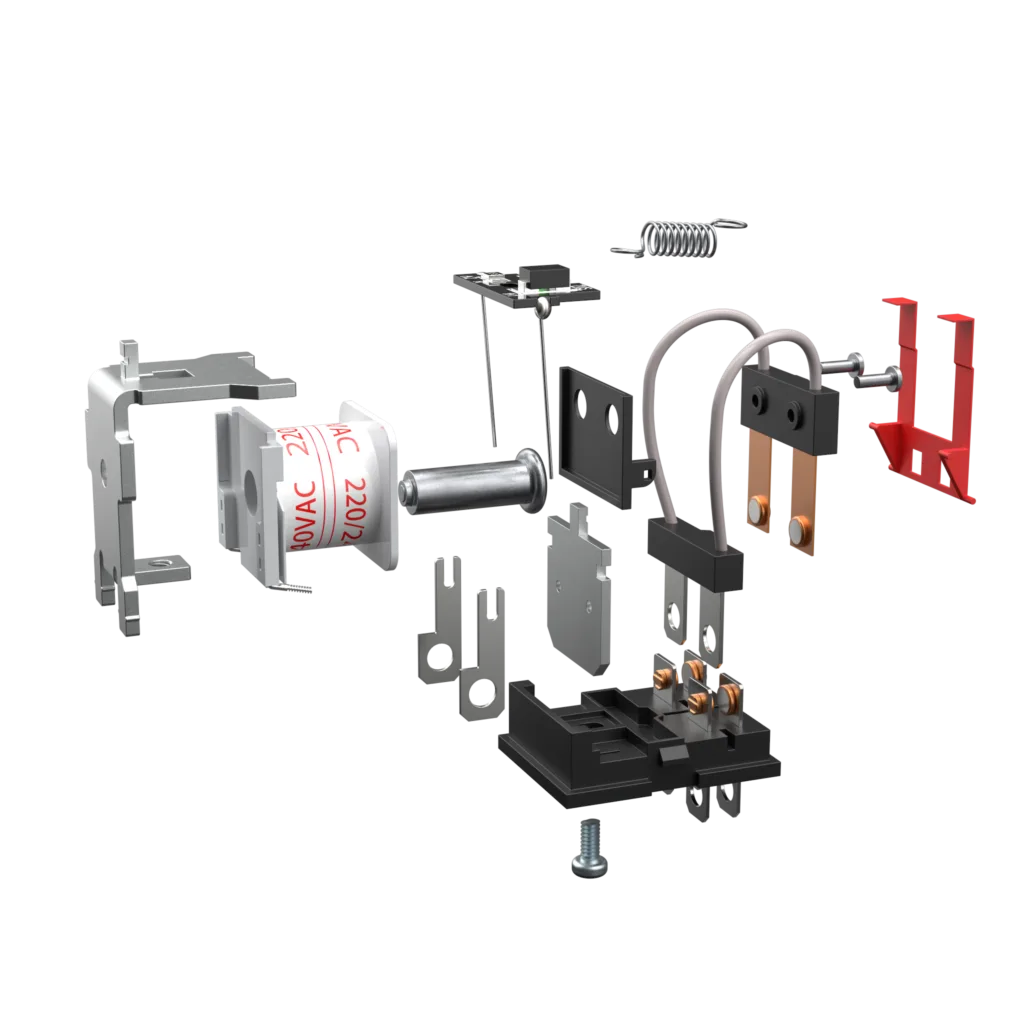
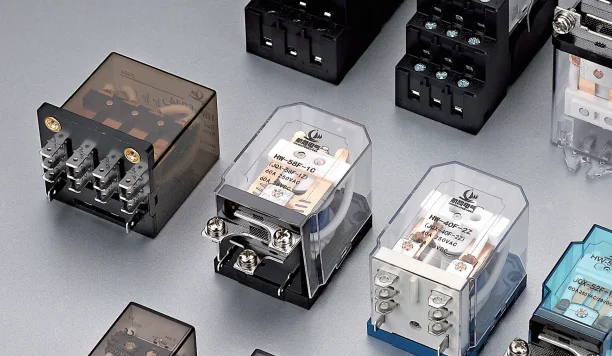
A HW-40F-2Z power relay switch has two sides: the coil side (control) and the contact side (load). Coil voltage refers to the rated voltage that must be applied to the coil to reliably energize the relay and change the contact state.
Most industrial power relay switches are available with multiple coil voltage variants—common choices include 5 VDC, 12 VDC, 24 VDC, 48 VDC, 110/120 VAC, and 220/230 VAC coils—while the contact side may be rated for much higher load voltages such as 250 VAC or more. The coil voltage rating is independent of the contact rating; you can easily have a 24 VDC coil operating a 400 VAC motor circuit through the contacts as long as the contact ratings are respected.
Key coil voltage parameters
Datasheets typically list several important coil‑related values that B2B engineers should check carefully.
These parameters define an “operating window” for reliable switching: above the pick‑up voltage the relay should energize, below the drop‑out voltage it should release, and between these values there is often a zone where behavior can be uncertain.
Table: Typical Coil Voltage Ratings And Uses
Choosing the wrong coil voltage for a power relay switch can cause surprisingly costly problems in B2B applications. If the coil voltage is too low for the supply, the relay may never energize; if the coil voltage is too high, the relay may appear to work but run hot, age quickly, or fail prematurely.
For OEMs and panel builders, reliability and safety are top priorities. A relay that fails to pull in under brown‑out conditions can stop an entire production line; a coil that overheats may pose a safety risk or fail regulatory testing. Long‑term stability is also critical for systems that must run 24/7 in harsh industrial environments, such as process plants, data centers, and HVAC equipment.
Impact on system design
Your coil voltage selection also affects upstream design decisions.
Table: Consequences Of Incorrect Coil Voltage
So how do you actually pick a coil voltage for your power relay switch in a real project? The good news is that the process is straightforward if you follow a simple checklist.
First, identify the control voltage rail you already have in your system.
As a general rule, select a relay coil rated for the control voltage you can provide easily and robustly, instead of introducing a new voltage rail just for the relay.
Table: Matching Coil Voltage To Control Supply
Next, consider how much your control voltage can vary in real life—under brown‑out conditions, start‑up surges, or long cable runs. Compare this range with the relay’s pick‑up and drop‑out voltage specifications.
For example, a 24 VDC coil may have a pick‑up voltage of about 70% of nominal (around 16–17 V) and a drop‑out voltage below 20–30% of nominal. In that case, as long as your 24 V supply never drops below the pick‑up threshold when the relay is supposed to energize, operation will be reliable. It is also important to make sure that any upper tolerance (for example, 28–30 V during charging) stays below the maximum continuous coil voltage in the datasheet.
Table: Example 24 VDC Coil Operating Range

Contact us for custom high-performance power relays Coil Voltage solutions tailored to your needs.
Coil power is another important factor, especially for high‑density panels or equipment with tight thermal budgets. Coil power is essentially the product of coil voltage and current; higher power means more heat inside the relay and inside your enclosure.
Often, higher voltage coils draw less current for the same sensitivity, which reduces the load on driver ICs and wiring resistance losses. However, lower‑power or “sensitive” coils are also widely available in many power relay switch families, giving you options to reduce holding power without changing the voltage rating. If your project involves large numbers of relays energized for long periods (for example, building automation or data center power distribution), selecting low‑power coils can help reduce total energy consumption.
Table: Example Coil Power Considerations
(Actual power values depend on the specific relay series and must be taken from datasheets.)
Power relay switches are available with both DC and AC coils, and they behave differently. DC coils are common in PLC‑based and low‑voltage electronic systems, while AC coils are popular in traditional line‑voltage contactors and HVAC equipment.
A DC coil typically needs a polarity‑correct DC supply, and its pick‑up and drop‑out behavior is defined with relatively tight thresholds. AC coils are designed to work with sinusoidal voltage and often tolerate a wider range of RMS voltage while managing inrush and holding characteristics differently. When selecting, always ensure the coil type (AC or DC) matches your available control power; applying AC to a DC coil or vice versa is unsafe and can quickly damage the relay.
Table: DC vs AC Coil For Power Relay Switches
While coil voltage is all about the control side, the power relay switch also has contact ratings that must match the load you are switching. Contact ratings usually specify maximum switching voltage, current, and power, and these are independent of the coil voltage selection.
For example, you can pair a 24 VDC coil with contacts rated at 250 VAC, 10 A for controlling pumps, heaters, or lighting circuits. As long as the coil voltage is suitable for your control system and the contact ratings exceed the demands of the load circuit, the combination is valid. This separation is what makes power relay switches so flexible in industrial applications.
Table: Example Power Relay Switch Configuration
When you are ready to specify coil voltage for your next power relay switch project, gather three key pieces of data—your control supply type, its tolerance range, and your thermal limits—and then choose a coil variant that matches those conditions with comfortable safety margins. If you share those parameters and your annual quantity, it is easy to recommend optimized power relay switch part numbers tailored to your B2B application.
No. The coil voltage must match your available control supply; a 24 VDC supply cannot reliably drive a 48 VDC coil, and attempting to work near the pick‑up threshold leads to unreliable operation.
Always check the datasheet’s maximum coil voltage; some relays allow a certain percentage above nominal, but continuous over‑voltage can cause excessive heating and shorter relay life.
Physically it may fit, but electrically it will not work unless your control supply is also changed to 24 VDC; always match the coil voltage to the actual control voltage.
Look at your system architecture: if 24 VDC is already the standard industrial control rail, a 24 VDC coil is usually more convenient and efficient, while 12 VDC is common in automotive and telecom systems.
For DC coils driven by electronics, a flyback diode or snubber is typically recommended to protect drivers from inductive voltage spikes when the coil is switched off.
A single relay part number normally has a single coil voltage option, but many relay families offer multiple variants; you simply select the appropriate coil voltage code when ordering.
Contact us for custom high-performance Power Relay Switchs Coil Voltage solutions tailored to your needs.
Learn how to evaluate a power relay manufacturer, compare relay types, understand pricing factors, and choose the right relay for OEM, export, and industrial sourcing projects.
Read More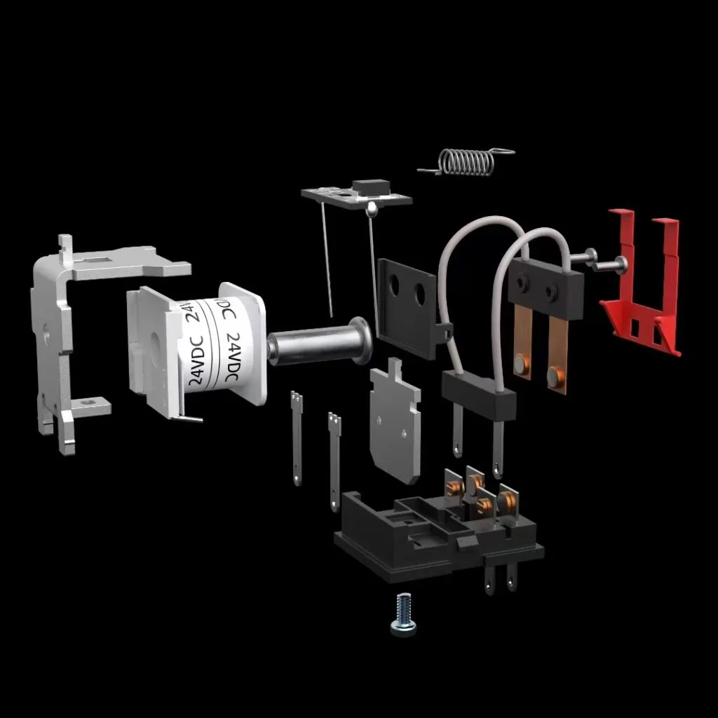
Looking for a reliable solution to manage your vehicle’s electrical system? The ECM power relay is a key component in modern automotive and industrial applications, ensuring efficient power delivery and control. Whether you’re sourcing parts for fleet maintenance, automotive repair, or industrial automation, understanding the role and benefits of ECM power relays can help you make smarter […]
Read More
Welcome to HW Relay knowledge hub! If you’re in the market for reliable control solutions or simply want to keep your procurement team savvy, understanding the ins and outs of both PCM Power Relays and main relays can give you a real edge. It’s a question that keeps popping up in engineer forums and RFP discussions: What exactly […]
Read More