Power relays are the workhorses that sit between your low‑voltage control logic and your high‑power loads, making sure motors, heaters, power supplies, and industrial machines switch safely and reliably on command. For B2B buyers, choosing the right power relay is not just a technical decision; it directly impacts safety approvals, maintenance cost, energy efficiency, and long‑term reliability in the field. This article walks through working principles, main components, contact types, and key differences, so you can specify confidently and send inquiries with clear technical requirements.
What is a power relays?
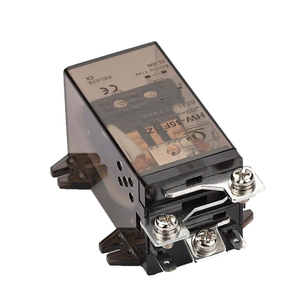
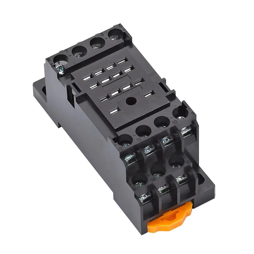
In simple terms, a HW-38F-3Z Power Relays is an electrically operated switch designed to control relatively high currents and voltages using a low‑power control signal. Compared with small signal relays, power relays focus on handling larger loads, providing isolation, and maintaining electrical endurance in demanding environments such as industrial control panels, EV chargers, UPS systems, and building automation.
For B2B applications, power relays appear across many product categories: industrial power relays, motor control relays, HVAC compressor relays, power distribution relays, and PCB power relays for compact power electronics. In all these cases, the core task is the same: switch power safely and repeatedly while keeping the control side and load side properly isolated.
Typical power relays parameters
Parameter
Description
Coil voltage
Rated control voltage (for example 5 VDC, 12 VDC, 24 VDC, 110 VAC).
Contact rating
Maximum switching current and voltage (for example 30 A at 250 VAC).
Contact configuration
NO, NC, or changeover (SPST, SPDT, DPDT, etc.).
Electrical life
Number of operations under rated load before failure.
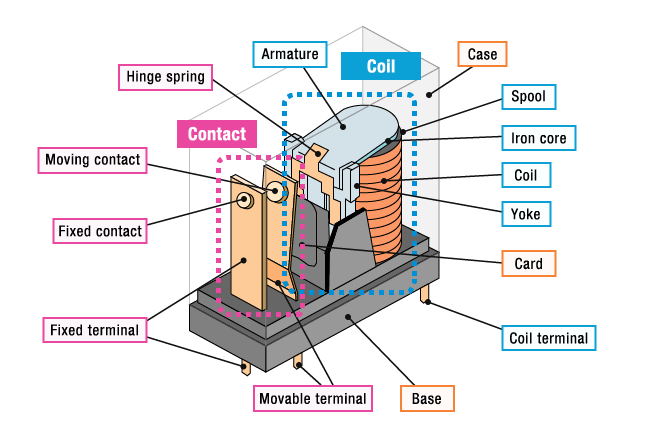
Most power relays used in industrial and power electronics are electromagnetic relays. The basic working principle is straightforward: a current in the coil generates a magnetic field, this field pulls an armature, and the armature opens or closes the power contacts to switch the load. When the coil is de‑energized, a spring or gravity returns the armature to its original position, restoring the default contact state.
From a system perspective, a power relay separates the control circuit (PLC output, microcontroller, thermostat, or driver) from the power circuit (AC mains, DC bus, or motor line). This galvanic isolation helps protect sensitive electronics from transients, and also allows low‑voltage logic (for example 5 VDC) to control high‑voltage lines (for example 400 VAC three‑phase) with appropriate relay selection.
Operation sequence overview
Step
What happens inside the relay
Coil energized
Control circuit applies voltage/current to coil.
Magnetic field
Coil current builds a magnetic field in the iron core.
Armature moves
Magnetic force pulls the armature towards the core.
Contacts change
NO contacts close, NC contacts open (or vice versa for latching types).
Coil off
Field collapses, spring returns armature, contacts revert to rest state.
For DC coils, the design is relatively simple, but for AC coils, the magnetic circuit may include a shading ring or shorted turn to prevent chatter when the AC waveform crosses zero. In higher‑end industrial power relays, this is important to reduce noise, contact bounce, and wear in applications like motor starters or safety interlock relays.
Main components of a power relay
Regardless of brand or series, most power relays HW-38F-3Z are built from the same basic blocks: coil, magnetic core, armature, spring mechanism, and contacts, enclosed in a protective housing. Understanding these parts helps B2B buyers evaluate quality, durability, and suitability for harsh environments such as high‑temperature cabinets or dusty workshops.
The coil defines the control interface and power consumption, while the contacts define how much current and voltage the relay can safely switch. The mechanical design of the armature and springs affects switching speed, endurance, and noise, which matters in applications like building automation, data center power management, and medical equipment where silent operation can be a selling point.
Key components and their roles
Component
Role in operation
Coil
Generates magnetic field when energized by control voltage.
Iron core
Guides and concentrates magnetic flux to pull the armature.
Armature
Moving metal lever that transfers force to the contacts.
Return spring
Resets armature and contacts when coil is off.
Contacts
Conduct or interrupt load current; made from wear‑resistant alloys.
Housing
Provides mechanical protection, insulation, and creepage distances.
If your project involves OEM production for industrial equipment, it is worth asking suppliers about contact material, silver alloy composition, and arc suppression design, since these details strongly influence life expectancy when switching inductive loads such as solenoid valves, pumps, and transformers. Many B2B customers include these as mandatory parameters in RFQs for industrial power relay modules or high‑current relay blocks.
Contact types in power relays
From the load side, the most important aspect of a power relay is its contact configuration and behavior. Different contact types support different control strategies, redundancy schemes, and safety functions in industrial automation and energy systems.
The simplest description uses NO (normally open) and NC (normally closed), but engineers often think in terms of SPST, SPDT, DPDT, or changeover contact sets. For example, power relays with SPDT contacts are popular in HVAC control boards because they can switch compressors or fans between modes, while DPDT power relays allow switching two isolated circuits simultaneously.
Common contact configurations
Contact type
Abbreviation
Description
Typical usage
Normally open
NO
Open at rest, closes when coil is energized.
On/off control of loads (motors, heaters, lamps).
Normally closed
NC
Closed at rest, opens when coil is energized.
Safety circuits, fail‑safe ventilation, alarms.
Changeover
SPDT / CO
One common contact switches between NO and NC terminals.
Signal switching, mode selection, simple interlocks.
In power relays, contact gap and creepage distances are critical for high‑voltage isolation and safety approvals (such as IEC or UL). When sourcing for OEM products that target international markets, many B2B customers require certificates and detailed test reports showing that the relay meets the required clearance, pollution degree, and overvoltage category.
Differences between contact types and how to choose
Although NO, NC, and changeover contacts look similar in datasheets, their behavior in failure and abnormal conditions can be very different. Choosing the wrong contact configuration may introduce safety risks, nuisance trips, or unwanted energizing of loads during power‑up or control failure in systems like elevators, cranes, and packaging lines.
For safety‑related circuits, designers often choose NC contacts in series for emergency stop loops, so that any broken wire or failed relay tends to put the system into a safe state. For energy management systems or smart building controls, NO contacts are common to minimize standby losses, with relays only energized when loads must be switched on.
Contact selection considerations
Design requirement
Preferred contact configuration
Reason
Fail‑safe emergency stop
NC contacts in series.
Any open circuit forces system to safe off state.
Standard load switching
NO contacts.
No voltage on load in normal rest state.
Alternate load or mode
SPDT changeover.
One relay switches between two outputs.
Multi‑phase or dual circuits
DPDT or 3‑pole contacts.
Synchronous switching of multiple lines.
Signal + power in one relay
Mixed contact blocks (power + auxiliary).
Power path plus feedback to PLC or controller.
For B2B procurement, it is good practice to specify not only the number of contacts, but also the functional behavior (for example “2 NO + 2 NC safety contacts with mirror contact function”) to avoid misunderstandings when comparing industrial safety relays and standard control relays in catalogs.
Contact us for custom high-performancepower relays solutions tailored to your needs.
Key types of power relays (electromechanical, solid‑state, latching)
When customers search for “power relays” today, they often mean several different technologies: electromechanical power relays (EMR), solid‑state relays (SSR), and latching relays. Each has its own strengths in terms of lifetime, isolation, control power, and cost, which B2B buyers should match to their application.
Electromechanical power relays remain the most common choice for general‑purpose AC and DC load switching because they offer clear physical isolation and competitive cost. Solid‑state relays, by contrast, use semiconductor devices to switch the load and shine in high‑frequency or low‑noise applications such as AC SSR modules for heaters or motor drives.
Temperature control, high‑cycle switching, cleanrooms.
Latching relay
Maintains state without continuous coil power.
Energy meters, smart home, battery‑powered devices.
Safety relay modules
Redundant contacts and monitoring.
Emergency stop circuits, guards, safety doors.
For OEMs in sectors such as EV charging, solar inverters, and industrial automation equipment, there is growing demand for high‑current DC power relays that can handle high‑voltage DC arcs, often incorporating special contact materials and arc blow‑out designs. These products are often marketed separately as “high voltage DC contactors” or “EV relays”, but they share many design concepts with traditional power relays.
Coil options: DC vs AC, single vs dual coil
From the control side, the choice of coil voltage and type affects the relay’s integration with PLCs, microcontrollers, and power supplies. Power relays are available with DC coils (5 V, 12 V, 24 V, 48 V, etc.) and AC coils (110 VAC, 230 VAC, or 24 VAC), each optimized for specific control architectures.
DC coils are common in low‑voltage control cabinets where a 24 VDC auxiliary supply is the standard; they also simplify interfacing with transistor outputs and relay drivers on PCB modules. AC coils are often used where the control comes directly from mains control circuits or traditional push‑button stations in industrial plants. Temperature affects coil resistance and therefore the pickup voltage, so many datasheets specify operation at a reference temperature such as 23 °C.
Coil characteristics and selection
Coil characteristic
Practical impact for B2B design teams
Coil voltage
Must match control system; mis‑match can cause non‑operation or overheating.
Coil power
Affects heat dissipation and energy use; important in dense cabinets.
Pickup/dropout values
Define safe operating window and noise immunity.
Single vs dual coil
Latching relays may use dual coils for set/reset control.
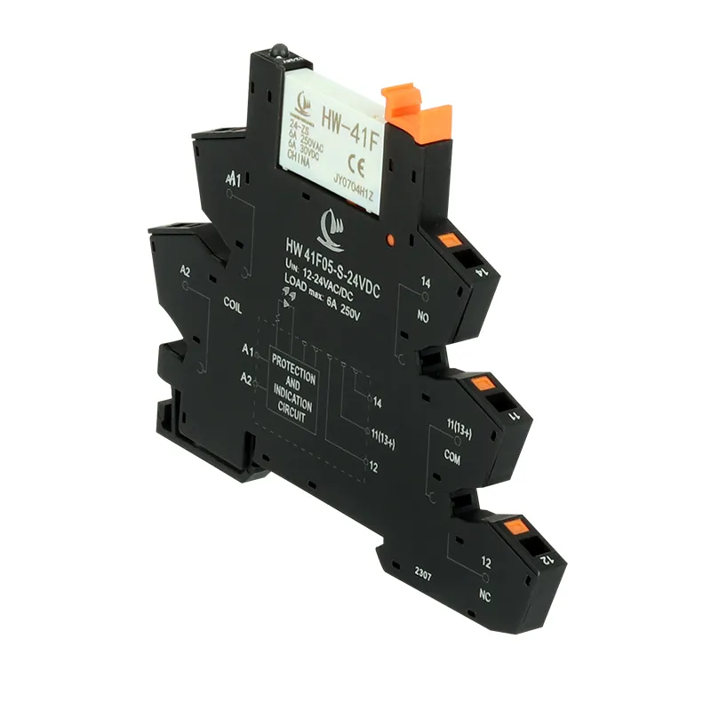
When sending RFQs for 24 VDC power relays or DIN‑rail power relay modules, it helps to specify control logic type (for example PLC transistor output, relay output, or manual switch) and acceptable coil power consumption to avoid over‑dimensioned solutions that run too hot in compact enclosures.
Application scenarios and B2B buying points
Power relays sit at the heart of many B2B products: motor control centers, industrial chillers, commercial HVAC units, power distribution units (PDUs), battery chargers, and more. Depending on the sector, buyers may prioritize different aspects such as switching capacity, approvals, mechanical form factor, or total cost of ownership.
Common high‑value long‑tail segments include HVAC compressor power relays, industrial pump control relays, power relays for PCB‑mount power supplies, and high‑power relay modules for machine tools. In each case, choosing correctly reduces warranty claims and downtime, which is why many B2B clients prefer to work with experienced relay manufacturers or solution providers who can assist in selection and customization.
Typical B2B application focus
Application segment
Key requirements
HVAC and refrigeration
High inrush current, wide temperature range, UL/IEC approvals.
Industrial automation
High reliability, DIN‑rail modules, PLC interface compatibility.
High voltage DC breaking, long life under DC arcs.
If your company is developing new equipment or looking for alternative suppliers to optimize cost, you can prepare a clear specification sheet (contact rating, coil voltage, approvals, mounting, and environment) and send it with your inquiry; this allows relay vendors to recommend matching series quickly and offer competitive quotations.
How to select the right power relay for your project
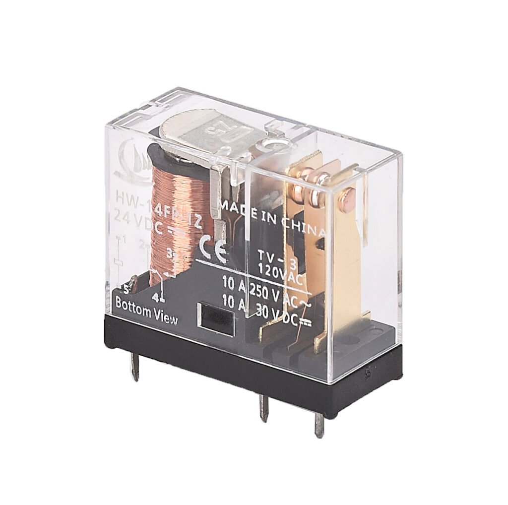
Selecting a power relay is not only about current and voltage; it’s about understanding the load type, environment, duty cycle, and safety requirements. For example, a 10 A resistive rating at 250 VAC does not automatically mean the relay can handle a 10 A motor load, because inductive loads create higher inrush currents and more severe arcing.
Engineers should also consider mechanical life and electrical endurance under real load profiles, including switching frequency and duty cycle. For high‑frequency switching or very long service life, it may be more cost‑effective to consider solid‑state relays or hybrid solutions, even if the unit price is higher than traditional electromechanical power relays.
Practical selection checklist
Factor
What to define before sourcing
Load type
Resistive, inductive, motor, capacitive, DC or AC.
Nominal load current
Normal operating current and expected inrush peaks.
Once these parameters are defined, B2B buyers can compare offers not just on price, but on lifetime cost, thermal performance, and service support, leading to better long‑term outcomes for both OEM and end customer. If you are ready to discuss a specific project or look for alternative part numbers to your current power relays, consider sending a brief project summary and your existing relay specifications so that a suitable cross reference can be recommended quickly.
FAQ
What is the difference between a power relay and a contactor?
A power relay is generally smaller and used for lower to medium current levels, while a contactor is designed for high‑current, frequent switching of motors and heavy loads, typically with more robust arc suppression and mechanical construction. In many light industrial and HVAC applications, high‑current power relays can replace small contactors to save space and cost when properly rated.
How do I choose between electromechanical and solid‑state power relays?
Electromechanical power relays are preferred where clear physical isolation, low leakage, and wide load compatibility are important, and where switching frequency is moderate. Solid‑state relays are ideal for high‑cycle switching, low noise, and precise control, but they can have higher on‑state losses and require careful thermal management.
Why do datasheets list different ratings for resistive and inductive loads?
Resistive loads draw nearly constant current, so arcing at the contacts is relatively mild, while inductive loads such as motors and transformers can create high inrush currents and significant voltage spikes when switching. To ensure long electrical life, manufacturers specify lower current ratings for inductive loads and recommend additional protection such as snubber circuits or varistors.
Can power relays be used for DC loads?
Yes, but DC switching is more challenging because the arc does not naturally extinguish at zero crossings as it does in AC systems. For high‑voltage DC or high‑current DC loads, special DC power relays or contactors with appropriate contact design and arc control should be selected.
What information should I include when sending an RFQ for power relays?
Include coil voltage, contact configuration, load type and rating, expected switching frequency, required approvals, and preferred mounting style. The clearer your requirements, the faster suppliers can propose suitable power relay models, samples, and pricing for your project.
Table of Contents
Contact us for custom high-performancepower relays solutions tailored to your needs.
Relay contacts are the unsung heroes of industrial automation, energy management, and transportation systems. Acting as the “switches” in electronic devices, they control current flow to enable automated operations. Have you ever wondered why relays perform differently under identical conditions? The secret lies in their contact configurations and material choices. In this guide, we’ll dive deep into relay […]
Power relay Contact are the hidden workhorses of industrial control. Their reliability hinges on the enduring quality of the contact set—the physical point where electrical energy meets mechanical action. This article dives deep into the contact structures and materials used in power relays, and provides practical guidelines to assess contact wear. Designed for B2B readers, […]
When someone types “Power Relay 40A, Dual Contacts, Rail Mount”, they not trying to write a PhD thesis. They want a relay that can survive real‑world loads, fit in a crowded control cabinet, and be easy enough for the wiring team not to swear at it. HW‑40F‑2Z sits exactly in that spot: a 40A power […]
We use cookies to enhance your browsing experience, serve personalised ads or content, and analyse our traffic. By clicking "Accept All", you consent to our use of cookies.
Get a Free Quote
Your email information is completely secure and will not be disclosed to third parties for any reason.
Interested In Our Relay Products?
Get the latest product brochures and technical data.