Understanding Relay & Wiring Diagrams
What is a Relay?
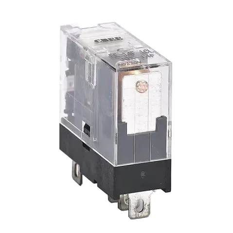
Hangwang Electrical HW-14F-1Z Relay is an electric switch, Understanding Relay & Wiring Diagrams, used to control the flow of current in a circuit. It uses a small electrical input to manage a larger electrical load, making it a crucial component in various applications. Relays are commonly found in household appliances, industrial machinery, and automotive systems, where they enable the automation of processes and ensure safety.
Relay typically operate through an electromagnet and a set of contacts. When electricity flows through the relay’s coil, it generates a magnetic field that activates the switch. This action changes the state of the contacts—either opening or closing them—to control the connected circuit. For instance, normally open (NO) contacts close to allow current flow, while normally closed (NC) contacts open to interrupt the current when activated.
Why Use a Relay?
Relays serve as essential components in electrical systems, enabling a low-current circuit to control one or more high-current circuits. Their design and functionality provide several advantages, making them indispensable in various applications:
- Efficient Wiring and Cost Savings: Relays allow the use of thinner cables to connect the control switch to the relay, reducing weight, space, and cost. This is particularly beneficial in automotive and industrial systems where compact designs are critical.
- Reduced Voltage Loss: By routing power to devices over shorter distances through relays, voltage loss is minimized. This ensures efficient energy transmission and enhances the overall performance of the system.
- Optimized Use of Heavy-Gauge Cables: With relays, heavy-gauge cables are only required between the power source and the device, reducing material costs and simplifying installation.
Why Use a Relay in a Car?
Relays play a vital role in automotive systems by enabling efficient control of high-current circuits using low-current signals. They offer several benefits that enhance the functionality, safety, and efficiency of a vehicle’s electrical system:
- Cost and Weight Efficiency: Relays eliminate the need for high-current-rated switches and thick cables in control circuits. This reduces the overall weight and cost of the wiring system while maintaining reliability.
- Flexible Placement: It can be mounted anywhere in the vehicle to efficiently deliver power to electronic accessories such as headlights, motors and heaters. This reduces voltage loss and ensures optimal performance.
- Protection for Switches and Wiring: By acting as intermediaries, relays prevent delicate switches from handling excessive electrical loads. This extends the lifespan of switches and protects wiring from overheating or damage.
- Enhanced Electrical Performance: Relays reduce resistance in electrical circuits, ensuring smoother current flow. For example, they help brighten car lights by minimizing voltage drops and improve the operation of components like cooling fans and fuel pumps.
- Versatility in Applications: Relays are used to control various systems in a car, including headlights (high-beam and low-beam), power windows, door locks, cooling fans, and even security systems. They enable seamless integration of these features while ensuring safety and efficiency.
How to understand the electrical specifications of your equipment
Relay are defined by several key electrical specifications, which are crucial for ensuring proper operation and avoiding damage. These specifications typically include ratings for the coil and the internal switching contacts. Here’s a breakdown of the main parameters:
- Coil Voltage Rating: This is the voltage required to energize the coil and activate its switching mechanism. Operating the coil outside its rated voltage can lead to malfunction or damage. For instance, a 12VDC should be powered with a voltage close to this nominal value for optimal performance.
- Switching Voltage and Current Ratings: The switching circuit of a relay has maximum voltage and current limits that must not be exceeded. These ratings indicate the maximum loads that the product contacts can safely handle.For example, exceeding these limits may result in arcing, degrade contact performance, or even damage the equipment.
- Contact Ratings: Double-throw relays often specify separate ratings for their normally open (N/O) and normally closed (N/C) terminals. For instance, a relay might be rated at 35A at 14VDC for N/O contacts and 20A at 14VDC for N/C contacts. These ratings reflect the maximum current each contact type can handle under specified conditions.
- Switching Capacity: This refers to the ability to handle specific loads over time. It combines both voltage and current ratings and is critical for determining the durability of the relay under actual operating conditions.
- Power Rating: Relays also have a maximum power rating, which is derived from their switching voltage and current limits. Exceeding this rating may shorten the service life or cause failure.
Why use protection devices?
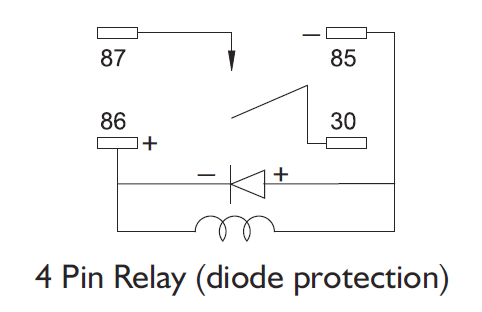
Protective devices are installed in the equipment to prevent voltage spikes generated when the coil is de-energized from damaging the control circuit.These spikes result from the sudden collapse of the magnetic field in the coil, which can generate high-voltage surges capable of harming sensitive electronic components. To mitigate this risk, resistors or diodes are often used as protective measures.
- Diodes for Protection: A diode is commonly placed across the equipment coil to absorb and dissipate the voltage spike. This prevents the surge from traveling back into the control circuit. Diodes are highly effective at eliminating these spikes, making them a preferred choice for sensitive systems. However, they require correct polarity during installation, as improper connections can damage the diode.
- Resistors for Protection: Resistors can also be used to suppress voltage spikes by absorbing some of the energy from the collapsing magnetic field. While less efficient than diodes at eliminating spikes, resistors are more durable and not polarity-sensitive, allowing for easier installation. They also allow a small current to flow, which can help reduce relay drop-out time.
- Choosing Between Diodes and Resistors: The decision to use a diode or resistor depends on the sensitivity of the control circuit and the specific application requirements. Diodes are ideal for highly sensitive circuits where maximum spike suppression is needed, while resistors may be suitable for less critical systems or where durability and ease of installation are prioritized.


What’s the Difference Between 4 and 5 Pin Relays?
The primary distinction between a 4-pin relay and a 5-pin relay lies in their functionality: a 4-pin relay controls a single circuit, while a 5-pin relay can switch power between two circuits. Below is an explanation of how each type operates:
4 Pin
- Configuration: A 4-pin uses two pins (85 and 86) to control the coil and two pins (30 and 87) to switch power in a single circuit.
- Types:
- Normally Open (NO): The circuit remains open (OFF) until the coil is energized, at which point it closes (ON), allowing current to flow.
- Normally Closed (NC): The circuit remains closed (ON) until the coil is energized, at which point it opens (OFF), stopping current flow.
- Use Case: Ideal for applications where only one circuit needs to be controlled, such as turning on lights or motors.
5 Pin
- Configuration: A 5-pin also uses two pins (85 and 86) to control the coil but includes three switching pins:
- Pin 30 (common terminal)
- Pin 87 (normally open terminal)
- Pin 87A (normally closed terminal).
- Functionality: When the coil is not energized, pin 30 is connected to pin 87A (NC). When the coil is activated, pin 30 switches to connect with pin 87 (NO). This allows the relay to switch between two circuits.
- Use Case: Useful for applications requiring power switching between two circuits, such as toggling between high and low beams in headlights or controlling multiple devices with a single relay.
Key Differences of Relay
| Feature | 4 Pin | 5 Pin |
|---|---|---|
| Number of Circuits | Controls one circuit | Switches power between two circuits |
| Switching Pins | Pins 30 and 87 | Pins 30, 87, and 87A |
| Default States | Either NO or NC | Includes both NO and NC connections |
| Applications | Simple on/off control | Multi-circuit control or toggling systems |
In summary, while both types of relays are used for switching electrical loads, a 4-pin is simpler and suited for single-circuit control, whereas a 5-pin offers greater flexibility by managing two circuits simultaneously.


