When buyers search for a 25v power relay wiring diagram, they usually do not want a textbook lecture. They want the answer to three plain questions: how do I wire it, how do I choose it, and which model should I buy so the project does not come back as an after-sales headache.
That is exactly how I look at it too. I have seen many relay discussions become strangely philosophical, as if a panel builder has time for poetry while a delivery deadline is staring at him. In real projects, the wiring diagram must help you land the coil correctly, assign the switching terminals correctly, and match the contact form to the load and cabinet layout.
There is one more useful reality check. On the web, most practical resources around this topic are labeled 24V relay wiring rather than 25V, so buyers searching for a 25v power relay wiring diagram often end up reading 24VDC relay material because the wiring logic is largely presented that way in industry references.
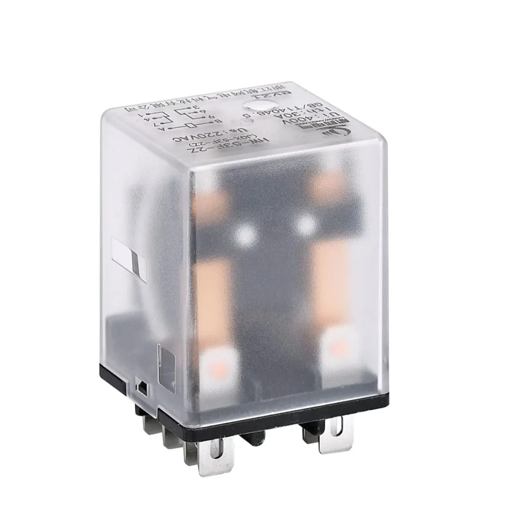
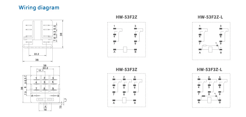
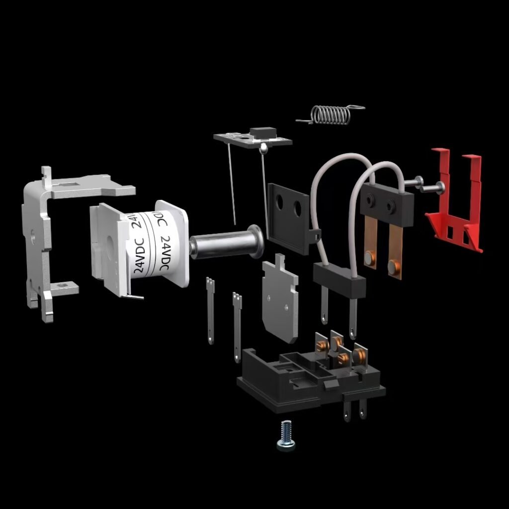
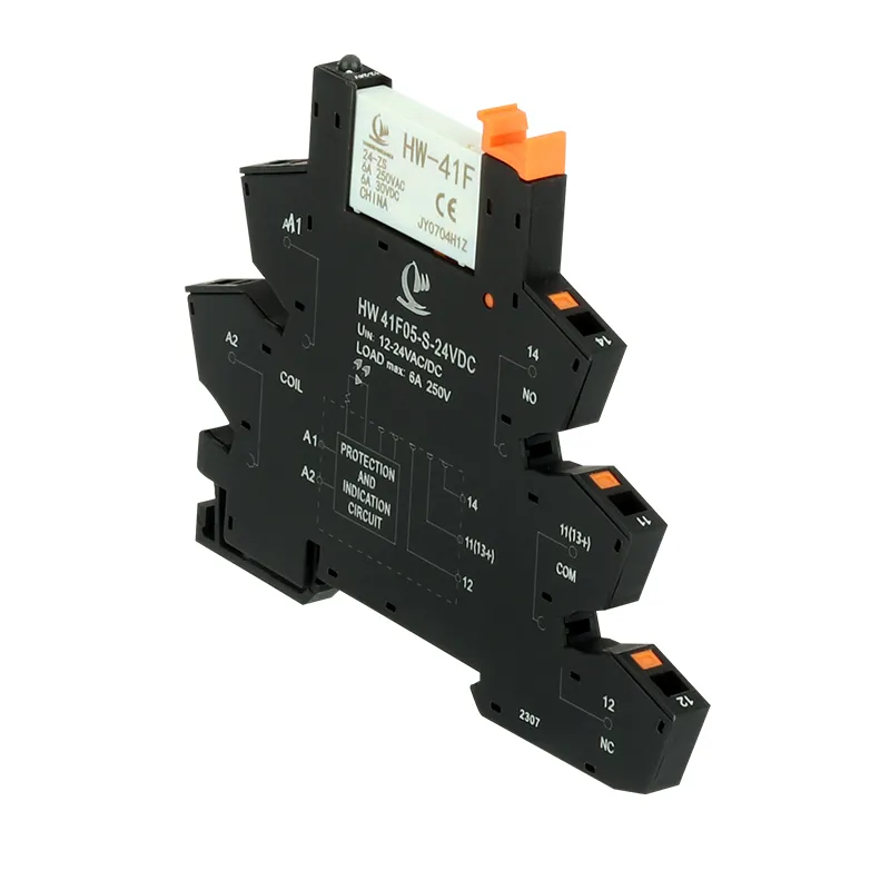
The wiring image you shared is already more useful than many catalog pages because it shows both the footprint and the internal contact layout of the HW-53F family. Specifically, it shows four variants: HW-53F-2Z, HW-53F-2Z-L, HW-53F-3Z, and HW-53F-3Z-L, alongside terminal dimensions and the A/B coil marking. For a procurement team, that means this is not just a relay picture; it is a purchasing filter for contact arrangement, installation space, and coil connection review before sampling.
In practical relay reading, the first rule is simple: identify the coil first, then read the switched contacts second. A common industrial convention is that A and B are the coil terminals, while numbered pins represent the switching contacts; one industrial 24VDC relay example explicitly uses A as positive and B as negative. Your HW-53F diagram follows that same visual logic by placing A and B at the coil and numbering the contact terminals separately.
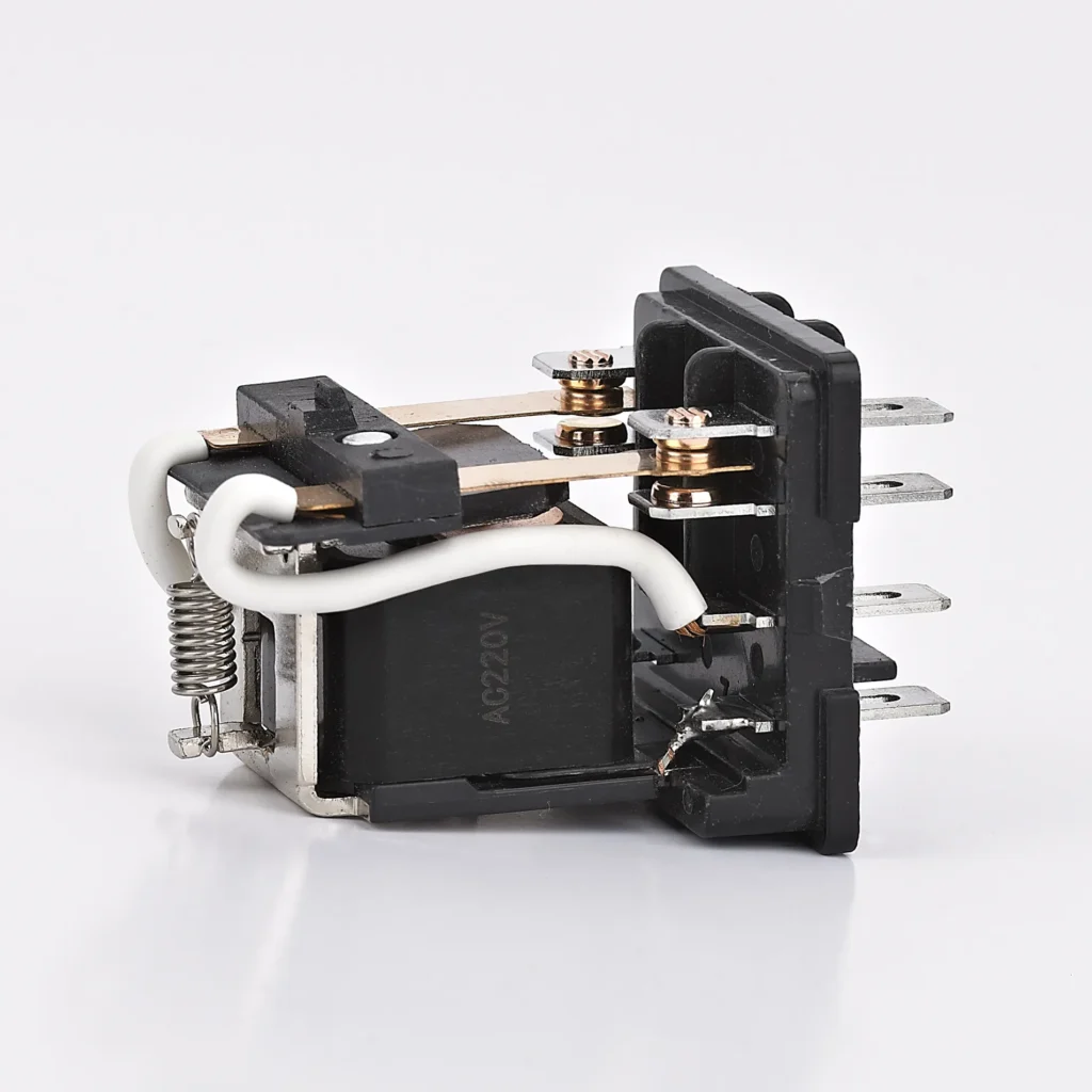
Another point buyers should not skip is coil polarity. Standard relay coils may have no polarity, but if the relay includes internal diode protection, polarity becomes important and the wrong connection can prevent operation or damage the protection path. That is why the phrase 25v relay coil polarity belongs naturally in this kind of article: it reflects a real buying concern, not keyword stuffing dressed up in a suit.
Diagram item
What it tells a buyer
Why it matters in procurement
HW-53F2Z / HW-53F2Z-L
Two related contact-layout variants are shown in the shared diagram.
Good fit when the application needs fewer switching paths and tighter panel planning.
HW-53F3Z / HW-53F3Z-L
A larger contact-layout family is also shown in the same drawing.
Useful when one relay must switch more than one control path in one device position.
A and B terminals
The coil is identified separately from the switching contacts.
This reduces wiring mistakes during assembly and incoming inspection.
Numbered terminals
The contact side is meant to be read by terminal numbers rather than by guesswork.
That is essential for harness drawings, test fixtures, and OEM documentation.
Polarity check
Coil polarity may matter when a diode-protected relay is used.
Buyers should confirm this before ordering for DC control systems.
Now let me say the quiet part out loud: the 25V Power Relay does not care how confident we feel. If the coil is miswired, confidence is just decorative. In a buyer-facing blog, that is where the keyword power relay wiring diagram for control cabinet becomes useful, because panel teams are not searching for theory; they are searching for fewer mistakes.
Wiring Method for 25V Power Relay in Actual Projects
A 25V power relay diagram becomes practical only when we translate it into an installation decision. In standard relay references, the coil circuit is read separately from the load circuit, and the contact side is then assigned as common, normally open, or normally closed depending on the internal diagram. That same reading method applies well to the HW-53F image because the coil and the contact sets are drawn as distinct functional blocks.
So how do I explain the 25v power relay wiring diagram to a purchasing manager or an engineering buyer? I keep it simple. First, confirm the control voltage of the cabinet and whether the team treats this as a 24VDC/25V-class control circuit. Second, check whether the coil side needs polarity attention. Third, match the contact count in the diagram to the number of independent switching paths required by the application. Those three checks prevent a surprising number of wrong orders.
Wiring decision
What to verify
Typical buyer concern
Coil connection
Read A and B first and confirm the control supply matches the intended relay coil use.
“Will this relay energize correctly in our DC control loop?”
Polarity
If there is internal diode protection, polarity matters and must be checked before assembly.
“Can our technicians reverse the wires by accident?”
Contact logic
Read the numbered contact terminals from the diagram instead of assuming a universal pinout.
“Will our harness match the sample and the mass-production lot?”
Load isolation
Relay references separate the coil circuit from the load circuit for correct control behavior.
“Can we safely switch the device without changing the control side?”
Documentation
Use the diagram in the RFQ and outgoing specification sheet.
“Can supplier, engineer, and assembler all read the same document?”
From a project standpoint, the 25V Power Relay wiring flow is less mysterious than it looks:
Read the coil side first by locating A and B on the diagram.
Confirm whether your relay version is polarity-sensitive before connecting a DC control line.
Read the numbered contact groups and assign each one to the actual load or control signal in the cabinet drawing.
Freeze that mapping in your BOM notes and test sheet so your supplier, your assembler, and your QA team are all speaking the same electrical language.
Which model to choose
The image makes one selection point immediately visible: this family is not one single relay with one single contact structure. It includes 2Z and 3Z variants, plus “-L” versions shown as separate internal layouts. For a buyer, that means choosing by price alone is risky, because the wrong contact arrangement can force rework in wiring, socket compatibility, or harness routing.
If your project only needs fewer control paths, the 2Z layout is usually the more efficient conversation to start with because the diagram presents a smaller switching arrangement than the 3Z version. If the application needs one relay to manage more interlocks, signals, or changeover paths, the 3Z drawing clearly offers more contact sections to work with. And if your project documents call out a specific layout variant, the “-L” versions should be treated as separate selection items rather than as interchangeable suffixes just because the names look friendly.
OEM power relay manufacturer, industrial power relay supplier, HW-53F-2Z bulk order, relay for EV auxiliary circuit, and control cabinet relay supplier.
Selection factor
2Z family
3Z family
Visual contact complexity
Fewer contact sections are shown in the shared diagram.
More contact sections are shown in the shared diagram.
Best starting point
Suitable when the control task is simpler and panel space discipline matters.
Suitable when one relay must handle more switching paths in the same product position.
Buyer risk
Wrong selection may leave the project short on usable contacts.
Wrong selection may increase complexity or space use beyond what is needed.
Variant caution
HW-53F2Z and HW-53F2Z-L should be checked as separate layouts.
HW-53F3Z and HW-53F3Z-L should also be checked as separate layouts.
RFQ note
Request the exact internal diagram in the quote package.
Request the exact internal diagram in the quote package.
When I help a customer narrow the choice, I normally ask four commercial questions before I ask ten electrical ones. What is the load? What is the control voltage? How many independent switching paths are needed? Does the production team want a 25v power relay family that is easy to substitute across projects? Those answers decide the shortlist much faster than a page full of abstract relay definitions.
And yes, this is the part where I gently remind buyers to send an inquiry contact us before they lock in the wrong version. A five-minute model confirmation is much cheaper than discovering at pilot build that the contact arrangement and the harness drawing are no longer on speaking terms.
FAQ
Is a 25v power relay wiring diagram basically read like a 24VDC relay diagram?
In practice, many reference materials explain the wiring logic through 24V relay examples, so buyers often use those materials to understand 25V-class control wiring structure.
What do A and B mean on the relay?
They indicate the coil side in the shared HW-53F diagram, and industrial examples also use A/B for the coil terminals.
Does coil polarity always matter?
No. It becomes especially important when the relay coil includes diode protection.
How do I decide between HW-53F2Z and HW-53F3Z?
Use the diagram to match the number of required switching paths to the internal contact layout shown for each version.
Should I treat the “-L” suffix as a separate model?
Yes, the shared diagram presents the “-L” versions as distinct internal layouts, so buyers should verify them separately in RFQs and sample approvals.
What is the safest way to read this diagram before purchasing?
I start with the coil, not the contacts. The reason is simple: standard relay references separate the activation side from the switching side, and that keeps the reading process clear and repeatable. Then I compare that logic with the shared HW-53F image, where A/B are isolated from the numbered terminals, so the wiring review becomes much easier.
Why do so many search results talk about 24V when my keyword is 25v power relay wiring diagram?
Because practical online relay material is commonly indexed around 24VDC examples, including general relay tutorials and industrial control examples. From an SEO and buyer-intent perspective, that means your article should naturally include related phrases like 24v dc power relay wiring and relay terminal diagram for control panel without losing focus on the main keyword.
What should a B2B buyer ask a supplier before ordering?
Ask for the exact internal contact diagram, coil terminal identification, polarity note if applicable, and confirmation that the production lot matches the approved drawing. The diagram you shared already shows why that matters: this family contains multiple internal layouts, not one universal version.
What kind of application benefits from this content strategy?
Any customer searching for an industrial power relay supplier, OEM power relay manufacturer, or HW-53F-2Z bulk order is usually evaluating more than one supplier and more than one equivalent model. A blog that explains wiring, selection, and model fit in one place supports both engineering confidence and commercial conversion.
Working principle of small relay A small relay is an electrical switch that operates using the principle of electromagnetic induction to control the on and off states of a circuit. It typically consists of four main components: a coil, an iron core, an armature, and contacts. When the coil is energized, current flows through it, generating a magnetic field. […]
Looking for a reliable solution to manage your vehicle’s electrical system? The ECM power relay is a key component in modern automotive and industrial applications, ensuring efficient power delivery and control. Whether you’re sourcing parts for fleet maintenance, automotive repair, or industrial automation, understanding the role and benefits of ECM power relays can help you make smarter […]
Choosing the right coil voltage for a power relay switch can feel tricky, especially when you are designing industrial control panels, OEM equipment, or automation systems for demanding B2B projects. You not only need the relay to pull in reliably, you also have to think about supply tolerance, safety, heat, and long‑term reliability. This guide […]
We use cookies to enhance your browsing experience, serve personalised ads or content, and analyse our traffic. By clicking "Accept All", you consent to our use of cookies.
Get a Free Quote
Your email information is completely secure and will not be disclosed to third parties for any reason.
Interested In Our Relay Products?
Get the latest product brochures and technical data.