Power relay Contact are the hidden workhorses of industrial control. Their reliability hinges on the enduring quality of the contact set—the physical point where electrical energy meets mechanical action. This article dives deep into the contact structures and materials used in power relays, and provides practical guidelines to assess contact wear. Designed for B2B readers, it blends engineering detail with actionable steps for procurement, maintenance, and lifecycle optimization.
Structures in Power Relay Contact
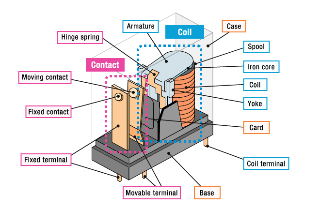
The power relay contact structure determines how current flows, how wear accumulates, and how easily a relay can suppress welding under surge. Here are the main structures you’ll encounter, with notes on where they excel and where they require care.
1️⃣Purely mechanical contact sets
Common in low-cost or compact relays. No fancy overtravel or wiping action unless specified.
Pros: simple, robust at low duty, easy to manufacture.
Cons: limited ability to handle high surge or arcing; higher contact resistance with wear.
Typical configurations to know: single blade, dual blade, and bifurcated contacts. These impact arc control and wiping behavior.
Quick tip: If your application sees frequent make/break cycles at moderate current, a robust mechanical contact design with defined wiping can reduce burn and resist stick-sliding wear.
2️⃣Wiped or wipe-enabled contact sets
Incorporates deliberate sliding movement during break or make to clean the contact surface.
Benefits: reduces contact resistance buildup, improves arc control, extends life under cycling loads.
Considerations: overtravel distance and geometry influence wipe effectiveness and mechanical stress.
Feature
Benefit
Caution
Wiping action
Cleaner contact surface, lower resistance after make/break
Requires precise tolerances; may increase mechanical wear if misdesigned
3️⃣Bipolar and bifurcated contact designs
Use two contact paths or split tips to distribute current and improve contact reliability.
Useful in high-current or high-load transitions where single-path contacts risk welding.
Design type
Best use case
Key consideration
Bipolar contact
High-current DC or AC loads with anticipated arcing
Ensure balanced current sharing
Biparted/bifurcated tips
Reduces welding risk for certain waveforms
Manufacturing tolerance is critical
4️⃣Overtravel and seating geometry
Overtravel is the extra movement after contact closure that helps wipe and seat the contact on first closure.
Proper overtravel reduces metal transfer and improves repeatability across cycles.
How to decide: match overtravel to contact force, load type, and expected number of cycles. Too little overtravel risks poor wiping; too much can wear springs and actuators.
Key takeaway
The right contact structure supports lower contact resistance, better arc suppression, and longer life under the exact load profile you face. In practice, many B2B buyers look first at structure compatibility with their duty cycle, then at material pairing for optimal life.
Contact Materials and Their Best-fit Scenarios
A practical material guide helps you match load, frequency, and environment to a durable contact. Below we summarize common materials and when they shine.
Silver alloys (Ag-based)
AgNi (silver-nickel, e.g., 90% Ag / 10% Ni): excellent for DC switching with high durability and resistance to material transfer; also used for low-inductive AC loads.
AgSnO2 (silver-tin oxide) and AgCdO: strong arc quenching and welding resistance for higher current and variable loads. AgCdO remains popular for resistive/inductive loads, while AgSnO2 offers improved thermal stability.
Pros: good conductivity, broad usability, strong wear resistance.
Cons: silver can migrate under certain conditions; wear resistance can vary with oxide formation depending on environment.
Palladium and other noble metals
Palladium contacts minimize tarnish and oxide formation, offering very low electrical noise and long life in compatible loads.
Best used where contact bounce control and low noise are critical and currents are moderate (often telecommunication-style relays).
Caution: conductivity is lower than pure silver alloys, so current ratings may be limited.
Phosphor Bronze: good wear resistance and corrosion resistance; commonly used as supporting springs and base contact materials.
Beryllium Copper: high-cycle life and good spring properties; used where repeated cycling and tight terminal requirements exist. Note higher cost.
Selection tip: for high-cycle, high-stress applications, copper-based alloys with proper treatment can outperform softer metals.
Tungsten and other exotic options
Tungsten: excellent arc erosion resistance; used for high-voltage, high-repetition environments; often paired with another contact material to offset oxide formation.
Mercury-contained or mercury-wetted designs exist but are niche and subject to regulatory considerations.
Upgrade your control system with top-quality power relays today!Discover reliable power relay solutions for your system.
Resistive loads: prioritize materials with stable contact resistance under steady current (AgCdO, AgSnO2).
Inductive loads: focus on welding resistance and arc-quenching capability (AgCdO, AgSnO2 variants; palladium for low-noise niches).
Mixed loads: consider bifurcated or bifurcated-tips with robust silver-based alloys that balance welding resistance and wear.
Practical table: quick matching guide
Load Type
Preferred Materials
Why
Common Trade-offs
Resistive
AgCdO, AgSnO2
High welding resistance; strong arc extinguishing
Higher cost; thermal considerations
Inductive
AgCdO, AgSnO2
Handles surge; arc suppression
Higher wear under continuous duty
Mixed/DC high current
AgNi, AgSnO2
Low transfer, good cycling
Cost and availability
Assessing Power Relay Contact Wear and When to Replace
Wear is a mix of mechanical, chemical, and thermal processes. A structured approach helps you predict remaining life and minimize downtime.
Signs of wear and failure modes
Rising contact resistance over cycles
Increased contact chatter or audible noise
Welds or material transfer observed on disassembly
Elevated temperature rise at the contact area
Surface pitting or corrosion in harsh environments
Field assessment workflow (simple, repeatable)
Baseline test: measure initial contact resistance with a known load.
Periodic tests: re-measure resistance at set intervals and compare to baseline.
Visual and thermal checks: inspect for discoloration, pitting, or abnormal heat signatures.
Fatigue analysis: estimate remaining life from cycle counts and load profiles.
Make a replacement decision based on a predefined threshold and cost-benefit analysis.
Step
Activity
Data to collect
Decision rule
1
Baseline
Contact resistance, leakage current
Compare to spec
2
Periodic checks
Temperature rise, audible noise
Trend analysis
3
Visual inspection
Surface condition, debris
Condition-based action
Diagnostic tools and methods
DC resistance measurement with calibrated equipment
IR thermography to spot hot spots
Vibration checks for mechanical looseness or stiction
Contact resistance ratio (CRR) as a life indicator
How to translate wear data into actionable maintenance Power Relay Contact
Create a maintenance schedule based on the predicted life from your data.
Build a parts-and-spares plan to minimize downtime during replacement.
Train operators to recognize early warning signs and document findings.
Tip: A well-documented wear history supports procurement teams when negotiating long-term service contracts and replacement part availability for your Power Relay portfolio.
Selection, Procurement, and OEM Messaging for Power Relay Contact
Great products start with clear specs and honest communication. Here are practical ways to align your technical content with B2B buyers’ needs.
Key specification areas to emphasize
Power Relay Contact material and recommended load types (resistive, inductive, capacitive)
Electrical life vs. mechanical life and the expected cycling
Swell resistance, humidity tolerance, and operating temperature range
Surge current capability and arc suppression performance
Packaging, mounting footprint, and replacement intervals
How to phrase claims for trust and clarity
Use measurable metrics: “Electrical life: X cycles at Y A, Z V” and “Contact resistance after life: <R ohms”
Provide failure modes and mitigations: “If arcing is observed, consider AgSnO2 for better arc suppression”
Include maintenance guidance: “Inspect quarterly; replace every N cycles or when resistance exceeds threshold”
This extended guide outlines how to present Power Relay contact structures, materials, and wear assessment in a way that is both informative and optimized for search.
FAQ
What is the typical lifespan of a Power Relay contact under high-cycle operation?
Lifespan depends on load type, current, and duty cycle. Typical electrical life ranges from tens to hundreds of thousands of cycles for common AgNi or AgSnO2 alloys, but exact figures should come from your product specs and life testing.
How can I reduce contact wear in a high-load relay?
Choose materials with strong wear resistance and arc suppression, ensure proper contact geometry, and implement wipe and overtravel techniques. Regular maintenance helps catch wear early.
Which materials are best for noisy, high-speed switching?
Palladium-containing contacts can offer low noise, but current ratings must be checked. For very high-speed switching with stringent noise limits, specialized materials and coatings may be required.
How should I structure my maintenance plan for Power Relays?
Start with a baseline life test, implement periodic resistance checks, set replacement thresholds, and align with your preventive maintenance schedule and spare parts strategy.
What is a Miniature Relay? A miniature relay is a small electromagnetic device designed to control circuit switches, allowing low-power signals to manage high-power loads. Unlike traditional relays, these devices are compact and lightweight, making them indispensable in modern electronics. With the growing demand for miniaturized and integrated systems, miniature relay have become critical components […]
In the world of electrical systems, relays play a crucial role in managing the flow of electricity and ensuring the smooth operation of circuits. Among these, PCM power relays are gaining significant attention, especially for their reliability and versatility in various industrial applications. This article aims to provide a detailed overview of PCM power relays, […]
In modern industrial automation systems, industrial relay contact serve as essential bridges for electrical control. At the heart of every relay are its contacts-the components responsible for making or breaking the circuit. The performance and reliability of these contacts directly impact the stability and safety of the entire system. Many relay failures can be traced […]
We use cookies to enhance your browsing experience, serve personalised ads or content, and analyse our traffic. By clicking "Accept All", you consent to our use of cookies.
Get a Free Quote
Your email information is completely secure and will not be disclosed to third parties for any reason.
Interested In Our Relay Products?
Get the latest product brochures and technical data.