Relay contacts are the unsung heroes of industrial automation, energy management, and transportation systems. Acting as the “switches” in electronic devices, they control current flow to enable automated operations. Have you ever wondered why relays perform differently under identical conditions? The secret lies in their contact configurations and material choices.
In this guide, we’ll dive deep into relay contact designs, materials, and their performance in high-frequency and high-load environments. Whether you’re an engineer or a procurement specialist, this article offers actionable insights to optimize your relay selection. Ready to unlock the potential of relay contacts? Let’s begin!
Relay Contact Basics
What Are Relay Contacts? Relay contacts are electrical connection points inside relays that open or close circuits. They come in three primary types:
Normally Open (NO): Closed only when the relay is activated.
Normally Closed (NC): Open when the relay is activated.
Changeover: Combines NO and NC contacts for circuit switching.
These contacts ensure safe and reliable device operation through mechanical movement.
How Relay Contacts Work
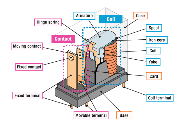
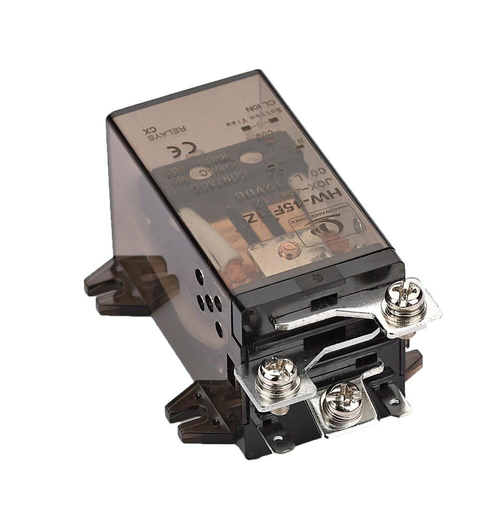
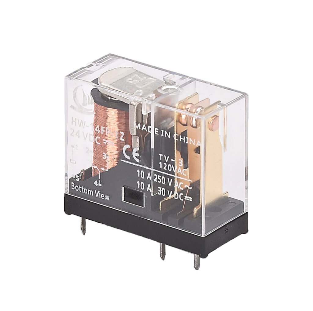
relay is an electrically operated switch. It usually consists of two main parts: a coil (electromagnet) and a set of contacts. When a small current flows through the coil, it creates a magnetic field. This magnetic field attracts a movable armature, which is mechanically linked to the relay contacts. As the armature moves, it either closes or opens the contacts, depending on the relay’s design.
Control Signal Applied: A low-power control signal is sent to the relay’s coil. This could come from a switch, sensor, or controller.
Magnetic Field Generated: The current through the coil generates a magnetic field, turning the coil into an electromagnet.
Armature Movement: The magnetic field pulls the armature towards the coil. This movement is often assisted by a spring that returns the armature to its original position when the coil is de-energized.
Contacts Switch: The armature’s movement causes the contacts to either close (complete the circuit) or open (break the circuit). For a normally open (NO) relay, the contacts close and allow current to flow to the load. For a normally closed (NC) relay, the contacts open and stop the current flow when the relay is activated.
Load Controlled: The relay contacts now control the flow of electricity to the load—this could be a light, motor, or any other device.
Relay Contact Configurations
The configuration of relay contacts directly impacts performance. Key parameters include:
Number of Contact Sets: Single for simple circuits, multiple for complex logic.
Contact Shapes:
Point Contact: Small area, ideal for low-current applications.
Line Contact: Larger area, better durability.
Surface Contact: Maximized area for high-current loads.
Dynamic vs. Static Contacts: Moving (dynamic) and fixed (static) contacts work together to maintain stable connections.
For example, industrial automation systems often use multi-line contacts to ensure signal stability.
Request samples and experience our reliable relay contact solutions.
Arc Erosion: Arcing during switching damages contact surfaces.
Welding: Contacts fuse due to excessive current.
Metal Migration: Material transfer alters contact performance.
Factors like material quality, contact pressure, load type, and environmental conditions affect lifespan. Regularly monitoring contact resistance helps detect issues early.
Material Performance in High-Frequency vs. High-Load Environments
Did you know? Material performance varies dramatically across environments:
High-Frequency Applications
Silver Nickel and Palladium Alloy excel due to low resistance and oxidation resistance.
Silver Tin Oxide works for medium frequencies but may attenuate signals at higher ranges.
High-Load Scenarios
Silver Cadmium Oxide dominates with superior arc resistance.
Silver Copper Nickel handles heavy currents in power equipment.
Material
High-Frequency Performance
High-Load Performance
Recommendation
Silver Nickel
Excellent
Moderate
Signal control systems
Palladium Alloy
Excellent
Weak
Communication devices
Silver Cadmium Oxide
Average
Outstanding
Industrial high-current use
Silver Copper Nickel
Average
Good
Heavy-duty equipment
Selecting the right material ensures stability in demanding conditions.
Relay contact configurations and materials are pivotal to device performance. Whether you’re tackling high-frequency signals or heavy loads, understanding these factors empowers smarter decisions
Need a tailored relay solution? Our expertise in custom contact designs and materials can optimize your equipment’s reliability. Contact us today for a consultation – let’s solve your relay challenges together!
FAQ
What does a relay coil symbol represent?
The coil symbol shows the electromagnetic part of the relay that activates the switching contacts when energized. It’s often drawn as a rectangle or circle.
What are common relay forms shown in symbols?
Form A is normally open; Form B is normally closed; Form C combines both NO and NC contacts in one relay for more versatile switching.
How do relay symbols help in circuit design?
They provide a visual shorthand that simplifies wiring, troubleshooting, and understanding relay operation in electrical schematics.
What is contact fusing and how to prevent it?
Contact fusing occurs when excessive current melts the contact surface, causing it to stick. Choosing relays with appropriate ratings and using protective circuits prevents this.
A Power Relay is a critical electrical device that acts as a switch, allowing a low-power circuit to control a high-power circuit safely and efficiently. Think of it as a middleman that controls heavy machinery or electrical loads without needing you to manually flip a switch every time. Power relays are extensively used in industrial […]
Industrial relay are indispensable components in automation control systems, and understanding Industrial Relay Symbol system is crucial for ensuring design quality, operational safety, and efficient troubleshooting. This guide offers a deep dive into the structure, application rules, and development trends of relay symbols. It draws on international standards (IEC 60617), domestic regulations (GB/T 4728), and […]
As a core component in industrial control and power systems, the performance and reliability of electromagnetic relays directly affect the safety and stability of equipment. With the increasing demand for automation and intelligence in modern industry, the selection and testing of electromagnetic relays have become a key link in engineering design. However, faced with complex […]
We use cookies to enhance your browsing experience, serve personalised ads or content, and analyse our traffic. By clicking "Accept All", you consent to our use of cookies.
Get a Free Quote
Your email information is completely secure and will not be disclosed to third parties for any reason.
Interested In Our Relay Products?
Get the latest product brochures and technical data.