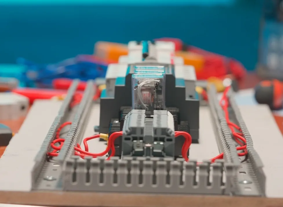
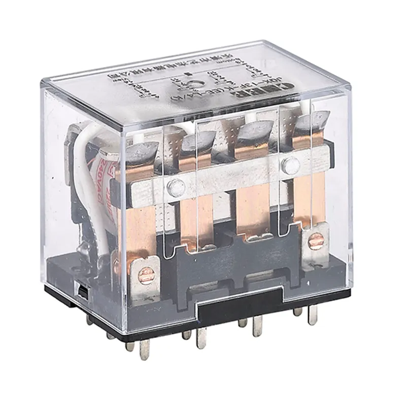
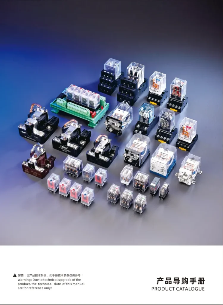
Definition of electromagnetic relay
An electromagnetic relay is an electrically controlled electromechanical component that uses electromagnetic effects to realize automatic switching devices for circuit control. It can operate the closing or opening of contacts by controlling the on and off of the coil, thereby realizing the connection or disconnection of the circuit.
The core function of an electromagnetic relay is to use weak current to control strong current and achieve electrical isolation. This makes it play an important role in automatic control systems and is widely used in industrial control, household appliances, communication equipment and other fields
Working principle
The working principle of electromagnetic relay is based on the law of electromagnetic induction:
When the coil is energized, an electromagnetic field is generated.
The electromagnetic field attracts the armature, overcoming the spring force to move the armature.
The armature drives the moving contacts, changing the contact state (closed or open).
When the coil is de-energized, the electromagnetic field disappears, and the spring force resets the armature.
The contacts return to their initial state.

Main technical parameters
| Parameter | Description |
|---|---|
| Rated Coil Voltage | Standard voltage for normal relay operation |
| Coil Resistance | DC resistance of the relay coil |
| Pick-up Voltage | Minimum voltage required for reliable relay activation |
| Pick-up Current | Minimum current required for reliable relay activation |
| Drop-out Voltage | Maximum voltage at which the relay reliably releases (typically 10-50% of pick-up voltage) |
| Drop-out Current | Maximum current at which the relay reliably releases |
| Contact Switching Voltage | Maximum voltage the relay contacts can switch |
| Contact Switching Current | Maximum current the relay contacts can switch |
| Contact Resistance | Resistance between normally closed contact and moving contact (should be 0); between normally open contact and moving contact (should be infinite) |
| Operate Time | Time from application of control signal to completion of contact action |
| Release Time | Time from removal of control signal to contacts returning to initial state |
| Mechanical Life | Number of operations the relay can reliably perform under no-load conditions |
| Electrical Life | Number of operations the relay can reliably perform under rated load conditions |
Electromagnetic relay contact types
Normally open contact
- When the Electromagnetic relay coil is not energized, the contact is in the open state
- The yellow circle at the bottom of the figure indicates the normally open contact
Normal closed contact
- When the relay coil is not energized, the contact is in the closed state
- The red circle at the bottom of the figure indicates the normally closed contact
Common contact
- Can be used with normally open or normally closed contacts
- Not clearly marked in the figure, but usually exists between normally open and normally closed contacts
Change-over contact
- Contains a common contact, a normally open contact and a normally closed contact
- Can achieve single-pole double-throw function
The contact configuration of the relay is usually:
- Single-pole single-throw: only one set of normally open or normally closed contacts
- Single-pole double-throw: one set of normally open and one set of normally closed contacts
- Double-pole single-throw: two sets of independent normally open or normally closed contacts
- Double-pole double-throw: two sets of independent change-over contacts

Precautions for using Electromagnetic relay
Pay attention to parameter matching when selecting:
- The coil voltage must match the control circuit voltage
- The contact capacity must be greater than the load current
- The working environment temperature must be within the allowable range of the Electromagnetic relay
Correct wiring:
- Pay attention to the positive and negative polarity of the coil wiring
- The contact wiring must distinguish between normally open and normally closed contacts
- The wiring must be firm to avoid virtual connection
Pay attention to electrical isolation:
- The control circuit and the load circuit must be electrically isolated
- Circuits of different voltage levels must be isolated
Protective measures:
- Install a protection diode to suppress the reverse electromotive force of the coil
- Add an RC absorption circuit to protect the contacts during high-frequency switching
- Dust-proof, moisture-proof, vibration-proof and other measures
Regular inspection and maintenance:
- Check whether the contacts are oxidized or ablated
- Measure whether the coil resistance is normal
- Clean the dust on the surface of the relay
Service life:
- Pay attention to the electrical life and mechanical life
- Appropriate derating should be used in occasions with frequent actions
Avoid overload:
- Do not exceed the rated voltage and current
- Pay attention to the impact of impact current on the contacts
Installation location:
- Keep away from heat sources and strong magnetic fields
- Leave gaps when multiple relays are installed side by side


